60
English
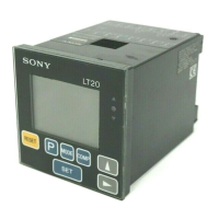
6. Terminals I/O
The terminals in the rear of the display unit have functions
for Go/No Go comparison, start input, reset input, and the
main power IN.
6-1. Connector pin assignment
Signal
(See P50 “4-3. Function description”.)
Pin
No.
1
2
3
4
5
6
7
8
9
10
11
12
13
14
Signal
Go/No Go output
High (A CH)
Go (A CH)
Low (A CH)
High (B CH)
Go (B CH)
Low (B CH)
Frame GND
Start/hold input
Reset/recall input
Main DC power (12 to 24V)
GND for power
Signal name
1 CH model 2 CH model
GND
HI HI (A)
GO GO (A)
LO LO (A)
Connection prohibited
HI (B)
Connection prohibited
GO (B)
Connection prohibited
LO (B)
GND
FG
START
RESET
DC IN 12 to 24V
GND
GND
Rear of display unit
• Use a shielded cable for connection to the FG pin on the
rear of the display unit.
(Prepare a shield cable by yourself.)
• GND (pins 1, 8, !£ and !¢) and FG (pin 9) are connected
with a capacitor. (isolated with respect to DC)
Outer cover
Knitted shield
Cross section of the cable
12345678
9 0 !¡ !™ !£ !¢
 Loading...