49
English
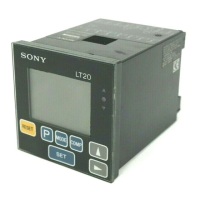
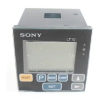
4-2. Rear panel
1 Terminals
(See P60 “6. Terminals I/O”.)
Input : Reset, peak-hold start, 12 to 24 V DC power IN.
Output: Go/No Go output.
2 DC IN
Connect 9 V AC adapter here.
3 Measuring probe input : SIG. IN A
4 Measuring probe input : SIG. IN B (2 channel models)
56 BCD Output
With the 2 channel models the upper and lower
selections of the front panel’s main display correspond
to the BCD OUT A/B.
So if “A+B” is selected the output is to BCD OUT A.
Input : Reset, peak-hold start,
comparator value selection (4 settings),
measuring mode (current value, maximum value,
minimum value, peak-to-peak values) selection
Output: 5 digits
Outputs one of the current, maximum,
minimum, and peak-to-peak values selected
via the keys on the front panel and the
external input.
Alarm output
1 channel-models 2 channel-models
12345678
9 1011121314
105/101
1
3
2
205/201
12345678
9 1011121314
4
105B/101B
12345678
9 1011121314
5
205B/201B
12345678
9 1011121314
6
105C/101C
12345678
9 1011121314
87
205C/201C
12345678
9 1011121314
 Loading...