48
English
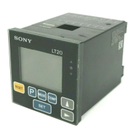
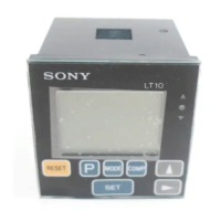
Main display
Displays the measured data, setting data for various
modes, or alarms, etc.
Preset status indicator
When P is displayed the preset value is set.
Peak-hold indicator
When MAX/MIN/P-P is displayed the data shown is the
maximum/minimum/maximum–minimum value.
When neither of the them is shown, the current value is
displayed.
Comparator upper limit setting indicator
Displayed when the comparator value has been set. The
upper digits are the upper limit.
Comparator lower limit setting indicator
Displayed when the comparator value has been set.
The lower digits are the lower limit.
• Up to four different comparator upper and lower limit
settings (CPH1 to CPH4 and CPL1 to CPL4) can be
stored in the memory for LT10-105B/205B and LT11-
101B/201B.
• LT10-105/205, 105C/205C and LT11-101/201, 101C/
201C have only one setting each.
Selected channel indicator (2 channel model)
Choose one of these two.
Upper A, A+B
Lower B
• A : data from measuring probe,
input channel A (rear of case)
B : data from measuring probe,
input channel B (rear of case)
A+B: sum of data from channel A and B
• In order to carry out calculations such as A–B or –A+B,
change the direction of A or B to “+” or “–”.
(Initial settings)
Comparator upper
limit setting indicator
Comparator lower
limit setting indicator
Selected channel indicator
Peak-hold indicator
Preset status indicator
mm
M A X M I N P ―P C P H1 2 3 4
P
mm
M A X M I N P ―P C P L1 2 3 4
P
A
B
 Loading...