— 8 —
4-1. Optical Power Meter
The optical power meter (ADVANTEST TQ8210) is used with the
optical sensor (ADVANTEST TQ82107) attached to it. Attach the
optical power meter to the BU adjustment jig after calibrating the
optical power meter.
Optical power meter setup
• POWER ....................................... ON
• W/dBm ........................................W
• MAX/dBr .................................... dBr
• λ .................................................. 780nm
• AUTO/MANUAL........................ AUTO
• SMOOTHING ............................. OFF
Calibration of optical power meter
1) Press the [AUTO/MANUAL] button of the optical power meter
to select the MANUAL mode.
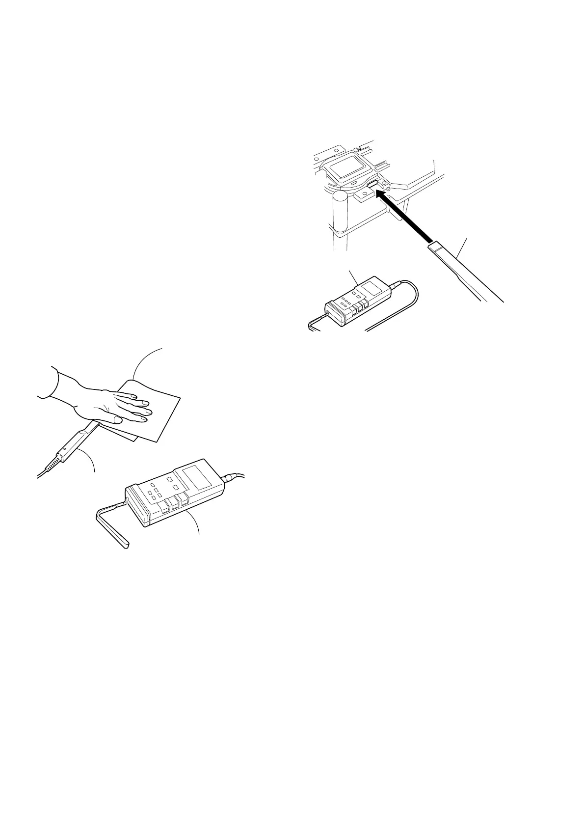
2) Slide the protective cover of the optical sensor to close it.
3) Cover the light measurement bock of the optical sensor with a
black paper. (Fig. 4-1-1)
4) Press the [ZERO] button of the optical power meter.
5) After the message “nuLL” appears on the optical power meter,
confirm that the display return to the optical power indication.
6) Press the [AUTO/MANUAL] button of the optical power meter
to select the AUTO mode.
Attaching the optical sensor to the BU adjustment jig
1) Open the disc cover of the BU adjustment jig and confirm that
any disc is not present in the jig.
2) Close the disc cover.
3) Insert the optical sensor into the deep end of the BU adjustment
jig as far as it can go shown in fig. 4-1-2.
Fig. 4-1-1
Fig. 4-1-2
4-2. Jitter Meter
Connect the Jitter meter (KIKUSUI KJM6235A) to the RF
connector of the BU adjustment jig.
Jitter meter setup
• IMPD........................................... 1MΩ
• SPEED ........................................ ×4
• TIME CONST ............................. 1S
• SYMMETRY .............................. FIXED
Optical power meter
Cover here with a
black paper
Optical sensor
Optical sensor
Optical power meter