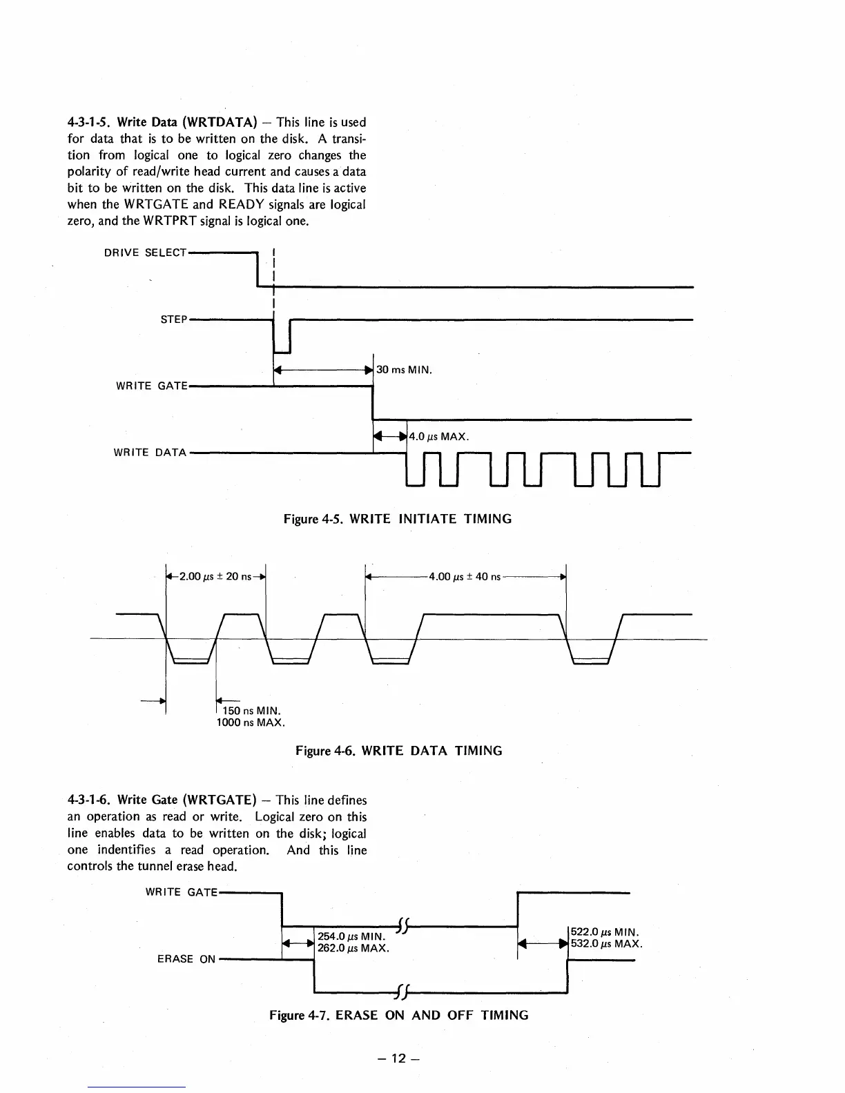
4-3-1-5. Write Data (WRTDATA) - This line
is
used
for
data
that
is
to
be written
on
the
disk. A transi-
tion from logical
one
to
logical zero changes the
polarity
of
read/write head
current
and causes a
data
bit
to
be written
on
the
disk. This data line
is
active
when the WRTGATE
and
READY signals are logical
zero, and
the
WRTPRT signal
is
logical one.
DRIVE
SELECT-----.
STEP-------.
~----_.t30msMIN.
WRITE
GATE-------------....,
WRITE
DATA
-----------
..........
-
......
Figure 4-5. WRITE INITIATE TIMING
~---4.00
J.LS
± 40
ns---~
150
ns
MIN.
1000
ns
MAX.
Figure 4-6. WRITE DATA TIMING
4-3-1-6. Write Gate (WRTGATE) - This line defines
an operation
as
read
or
write. Logical zero
on
this
line enables data
to
be written on
the
disk; logical
one
indentifies a read operation. And this line
controls
the
tunnel erase head.
WRITE
GATE---
__
9---,.....-----1.
(~--------f
....
522.0
J.Ls
MIN.
ERASE
ON
-
__
......
1.---1
254.0
J.LS
MIN.
262.0
J.LS
MAX.
J.-~f-----1~
..
532.0
J.Ls
MAX.
------~(~----------------~
Figure 4-7. ERASE ON AND
OFF
TIMING
-
12-
 Loading...