SECTION 7
ELECTRICAL CONNECTORS
7-1.
POWER
CONNECTOR
7 -1-1. Frame Ground
The drive unit should
be
frame grounded to the
host system. A frame ground screw for this purpose
is
provided on the back
of
the unit.
7 -1-2.
DC
Power Connector
(2)
DC
power connector (j2)
is
a 4-pin male plug which
is
located
at
the rear
of
the drive unit. This connec-
tor
should
be
used
to
satisfy the power requirements
of
the unit.
7 -1-3.
DC
Power Cable Fabrication
The
DC
power from the host system should
be
delivered to the drive unit over a cable with the
following recommended parts:
Receptacle (4-pin)
AMP
171822-4
Contact
Wire
AM
P 170262-1
AWG
20 (or equivale,nt)
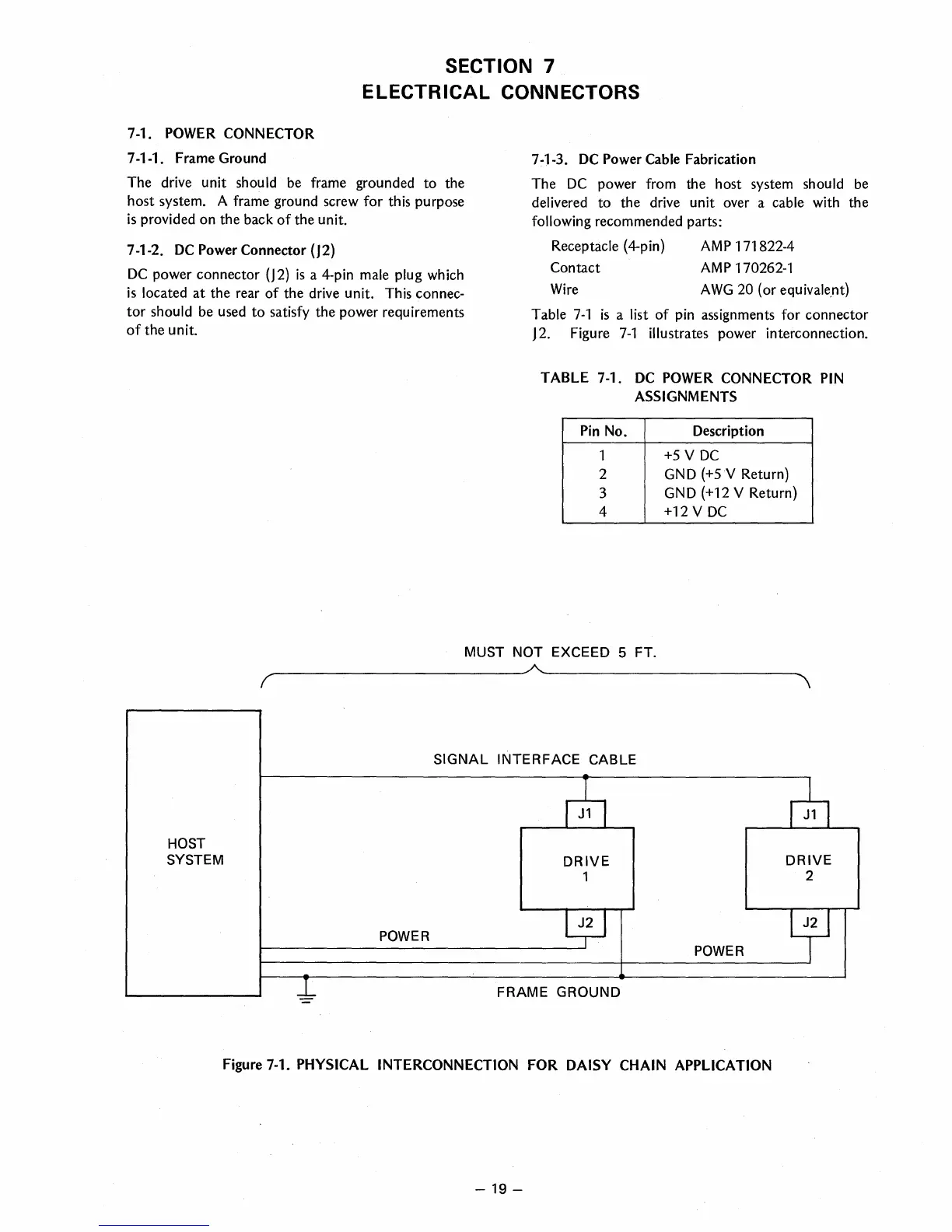
Table
7-1
is
a list
of
pin
assignments for connector
J2. Figure
7-1
illustrates power interconnection.
TABLE 7-1.
DC
POWER
CONNECTOR
PIN
ASSIGNMENTS
Pin
No.
Description
1
+5
V
DC
2
GND
(+5
V Return)
3
GND
(+12
V Return)
4
+12
V
DC
MUST
NOT
EXCEED
5
FT.
---------------------------~~--------------------------
( \
SIGNAL INTERFACE
CABLE
~
~
HOST
SYSTEM
DRIVE
DRIVE
1
2
POWER
-~
Y
POWER
-L
FRAME
GROUND
Figure 7-1.
PHYSICAL INTERCONNECTION FOR DAISY
CHAIN
APPLICATION
-
19-
 Loading...