SECTION 4
INTERFACE
DESCRIPTION
4-1.
HOST
SYSTEM
INTERFACE
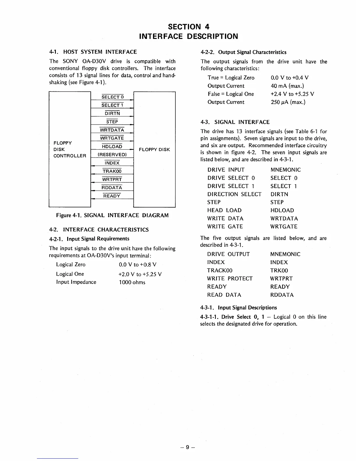
The
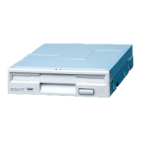
SONY
OA-D30V drive
is
compatible with
conventional floppy disk controllers. The interface
consists
of
13
signal
lines for data, control and hand-
shaking
(see
Figure
4-1
).
SELECT
0
SELECT
1
--
DIRTN
--
STEP
WRTDATA
WRTGATE
FLOPPY
DISK
HDLOAD
FLOPPY
DISK
CONTROLLER
(RESERVED)
--
INDEX
TRAKOO
WRTPRT
RDDATA
READY
Figure 4-1. SIGNAL INTERFACE
DIAGRAM
4-2. INTERFACE CHARACTERISTICS
4-2-1. I nput Signal Requirements
The input
signals to the
drive
unit
have
the following
requirements at OA-D30V's input terminal:
Logical
Zero 0.0 V to +0.8 V
Logical
One +2.0 V to +5.25 V
Input Impedance
1000
ohms
-9-
4-2-2. Output Signal Characteristics
The output signals from
following characteristics:
True =
Logical
Zero
Output Current
False
=
Logical
One
Output Current
the drive unit
have
the
0.0 V to +0.4 V
40
mA
(max.)
+2.4 V to +5.25 V
250
p.A
(max.)
4-3.
SIGNAL INTERFACE
The drive
has
13
interface signals
(see
Table
6-1
for
pin
assignments).
Seven
signals
are input
to
the drive,
and
six
are output. Recommended interface circuitry
is
shown
in
figure 4-2. The
seven
input signals are
listed below, and are described
in
4-3-1.
DRIVE
INPUT
MNEMONIC
DRIVE SELECT 0
SELECT 0
DRIVE SELECT
1
SELECT 1
DIRECTION SELECT
DIRTN
STEP STEP
HEAD
LOAD
HDLOAD
WRITE
DATA
WRTDATA
WRITE
GATE
WRTGATE
The
five
output signals are listed below, and are
described
in
4-3-1.
DRIVE OUTPUT
INDEX
TRACKOO
WRITE
PROTECT
READY
READ
DATA
MNEMONIC
INDEX
TRKOO
WRTPRT
READY
RDDATA
4-3-1. Input Signal Descriptions
4-3-1-1.
Drive
Select 0, 1 -
Logical
0 on th
is
line
selects the designated drive for operation.
 Loading...