7-2. SIGNAL INTERFACE CONNECTOR
7 -2-1. Signal I nterface Connector
(J
1 )
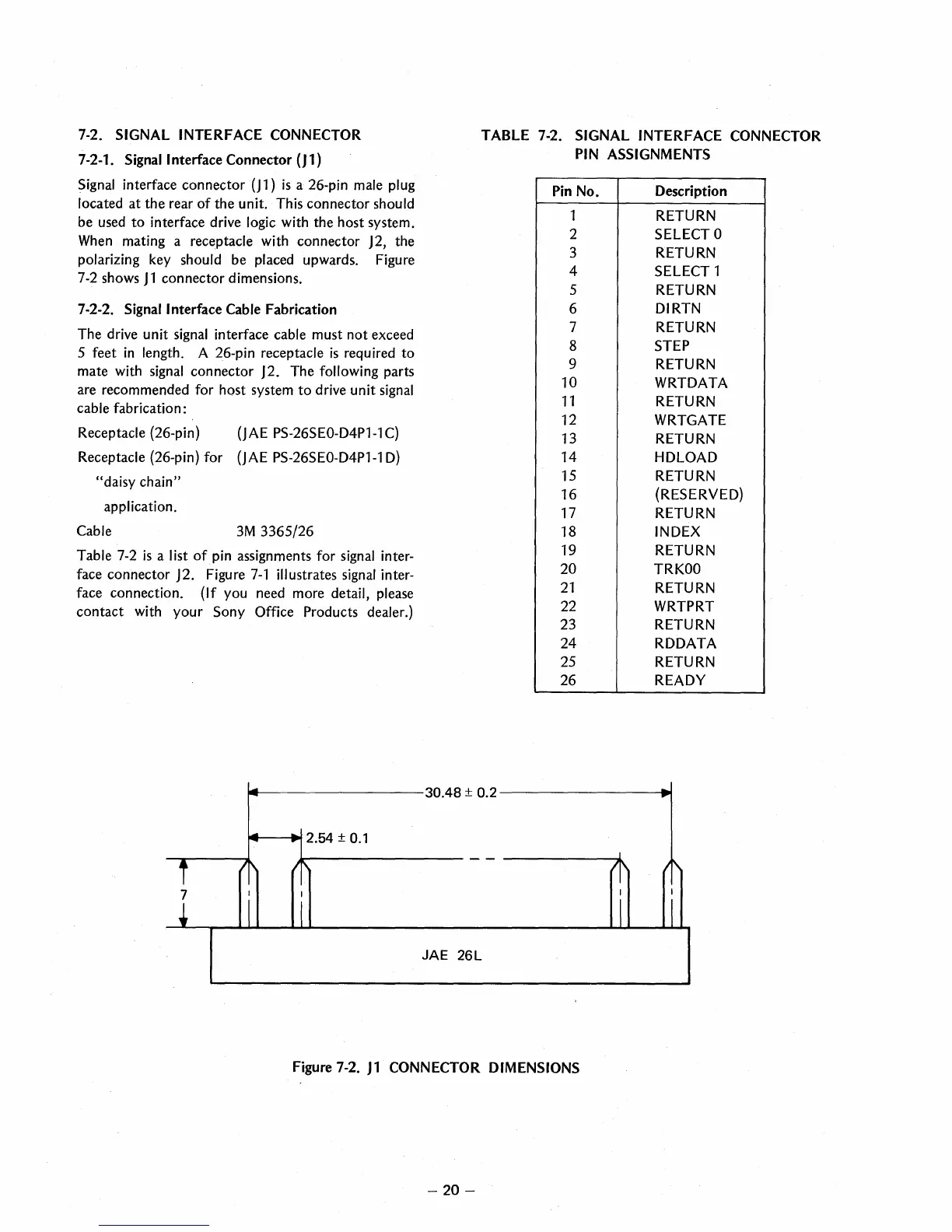
Signal
interface connector (j 1)
is
a 26-pin male plug
located at the rear
of
the unit. This connector should
be used to interface drive logic with the host system.
When
mating a receptacle with connector J 2, the
polarizing key should be placed upwards. Figure
7
-2
shows J 1 connector dimensions.
7-2-2.
Signal Interface Cable Fabrication
The drive unit
signal
interface cable must not exceed
5 feet
in
length. A 26-pin receptacle
is
required to
mate with
signal
connector J2. The following parts
are recommended for host system
to
drive unit
signal
cable fabrication:
Receptacle (26-pin)
(JAE
PS-26SEO-D4P1-1C)
Receptacle (26-pin) for
(JAE
PS-26SEO-D4P1-1D)
"daisy chain"
application.
Cable
3M
3365/26
Table
7-2
is
a list
of
pin
assignments for
signal
inter-
face connector J2. Figure
7-1
illustrates
signal
inter-
face connection. (If you need more detail, please
contact with your
Sony Office Products dealer.)
:..
-
.-
..
2.54 ±
0.1
...
...
i
Ir\ Ir\
7
I
I
j
I I
TABLE 7-2. SIGNAL INTERFACE CONNECTOR
PIN
ASSIGNMENTS
Pin
No.
Description
1 RETURN
2
SELECT 0
3 RETURN
4
SELECT 1
5
RETURN
6
DIRTN
7
RETURN
8
STEP
9
RETURN
10
WRTDATA
11
RETURN
12
WRTGATE
13 RETURN
14
HDLOAD
15
RETURN
16
(RESERVED)
17
RETURN
18
INDEX
19 RETURN
20
TRKOO
21
RETURN
22
WRTPRT
23 RETURN
24
RDDATA
25 RETURN
26 READY
30.48 ± 0.2
--
...
- -
J
l'
1\
I
I
I I
JAE 26L
Figure 7-2. J 1 CONNECTOR DIMENSIONS
-
20-
 Loading...