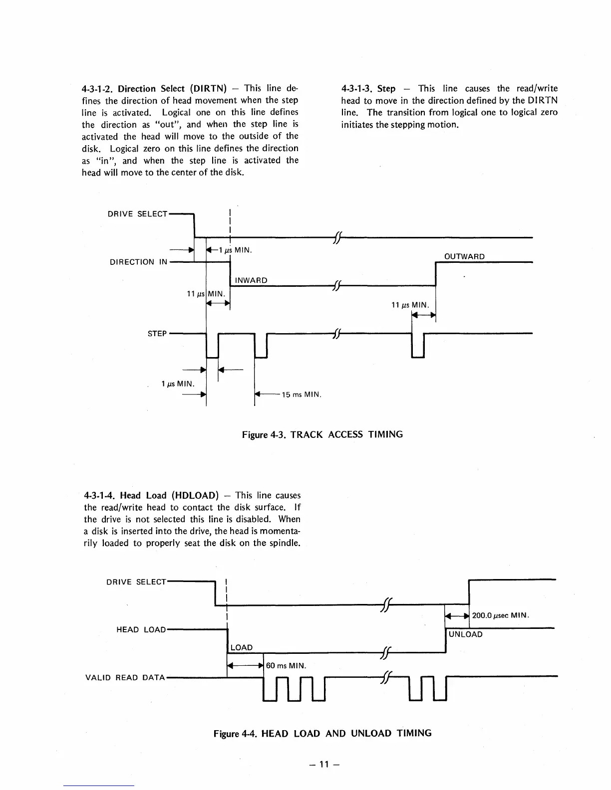
4-3-1-2. Direction Select (DI RTN) - This line
de-
fines the direction
of
head movement when
the
step
line
is
activated. Logical one on this line defines
the
direction
as
"out",
and when
the
step line
is
activated
the
head
will
move
to
the
outside
of
the
disk.
Logical zero
on
this line defines
the
direction
as
"in",
and when the step line
is
activated the
head
will move
to
the
center
of
the
disk.
DRIVE
SELECT
4-3-1-3.
Step
- This line causes the read/write
head
to
move
in
the
direction defined by
the
DI
RTN
line.
The
transition from logical
one
to
logical zero
initiates
the
stepping motion.
~~--+-----------------~~(---------------------------------
y
DIRECTION IN
---'~I-----6
11
J.lS
MIN.
STEP
----.I
15
ms
MIN.
Figure 4-3. TRACK ACCESS TIMING
4-3-1-4. Head Load (HDLOAD) - This line causes
the
read/write head
to
contact
the disk surface. If
the
drive
is
not
selected this line
is
disabled. When
a disk
is
inserted
into
the
drive,
the
head
is
momenta-
rily
loaded
to
properly seat
the
disk on
the
spindle.
DRIVE
SELECT------
HEAD
LOAD------.
LOAD
14---..60
ms
MIN.
VAll
DREAD
DATA
---------"""------"""
Figure 4-4. HEAD LOAD AND UNLOAD TIMING
-
11
-
OUTWARD
200.0
J.lsec
MIN.
UNLOAD
 Loading...