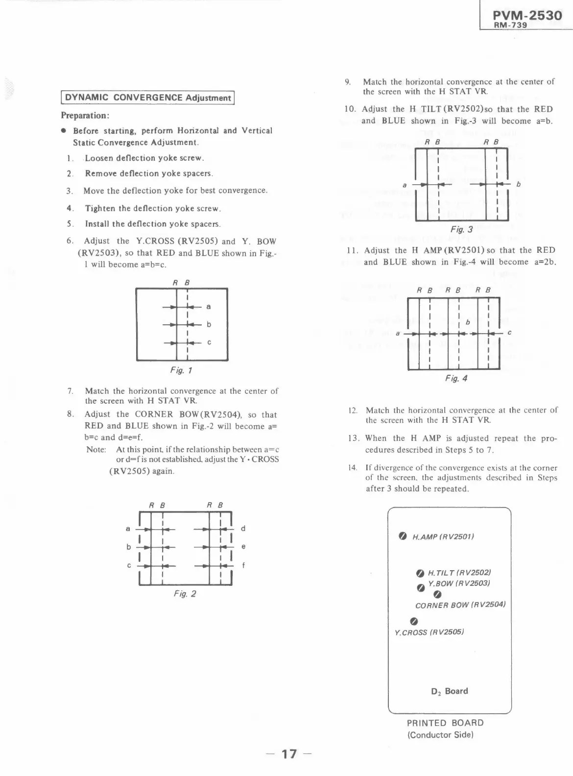
I DYNAMIC CONVERGENCE Adjustment I
Preparation:
• Before starting, perform Horizontal and Vertical
Static Convergence Adjustment.
l. Loosen deflection yoke screw.
2. Remove deflection yoke spacers.
3. Move the deflection yoke for best convergence.
4. Tighten the deflection yoke screw.
5. Install the deflection yoke spacers.
6. Adjust the Y.CROSS (RV2505) and Y. BOW
(RV2503), so that RED and BLUE shown in Fig.-
I will become a=b=c.
R 8
I
I
-
I
a
I
I -
b
-
.
I
I
C
-
-
I
I
Fig. 1
7. Match the horizontal convergence at the center of
the screen with H ST AT YR
8. Adjust the CORNER BOW(RV2504), so that
RED and BLUE shown in Fig.-2 will become a=
b=c and d=e=f.
Note: At this point, if the relationship between a=c
or d=f is not established adjust the Y • CROSS
(RV2505) again.
R 8
R B
d
e
Fig. 2
- 17 -
PVM-2530
RM-739
9. Match the horizontal convergence at the center of
the screen with the H ST AT YR
10. Adjust the H TILT (RV2502)so that the RED
and BLUE shown in Fig.-3 will become a=b.
R 8 R 8
I
I
I
I
I
I
I
I
a
-
-
-
p
I -
-
, -
b
I
I
I
I
I
I
I
I
Fig. 3
11. Adjust the H AMP (RV2501) so that the RED
and BLUE shown in Fig.-4 will become a=2b.
RB RB RB
b
Fig. 4
12. Match the horizontal convergence at the center of
the screen with the H ST AT YR
13. When the H AMP is adjusted repeat the pro-
cedures described in Steps 5 to 7.
14. If divergence of the convergence exists at the corner
of the screen. the adjustments described in Steps
after 3 should be repeated.
/
0 H.AMP (RV2501)
0 H. TILT (RV2502)
O Y. BOW ( R V2503)
0
CORNER BOW (RV2504)
0
Y.CROSS (RV2505)
D
2
Board
PRINTED BOARD
(Conductor Side)
_/
 Loading...