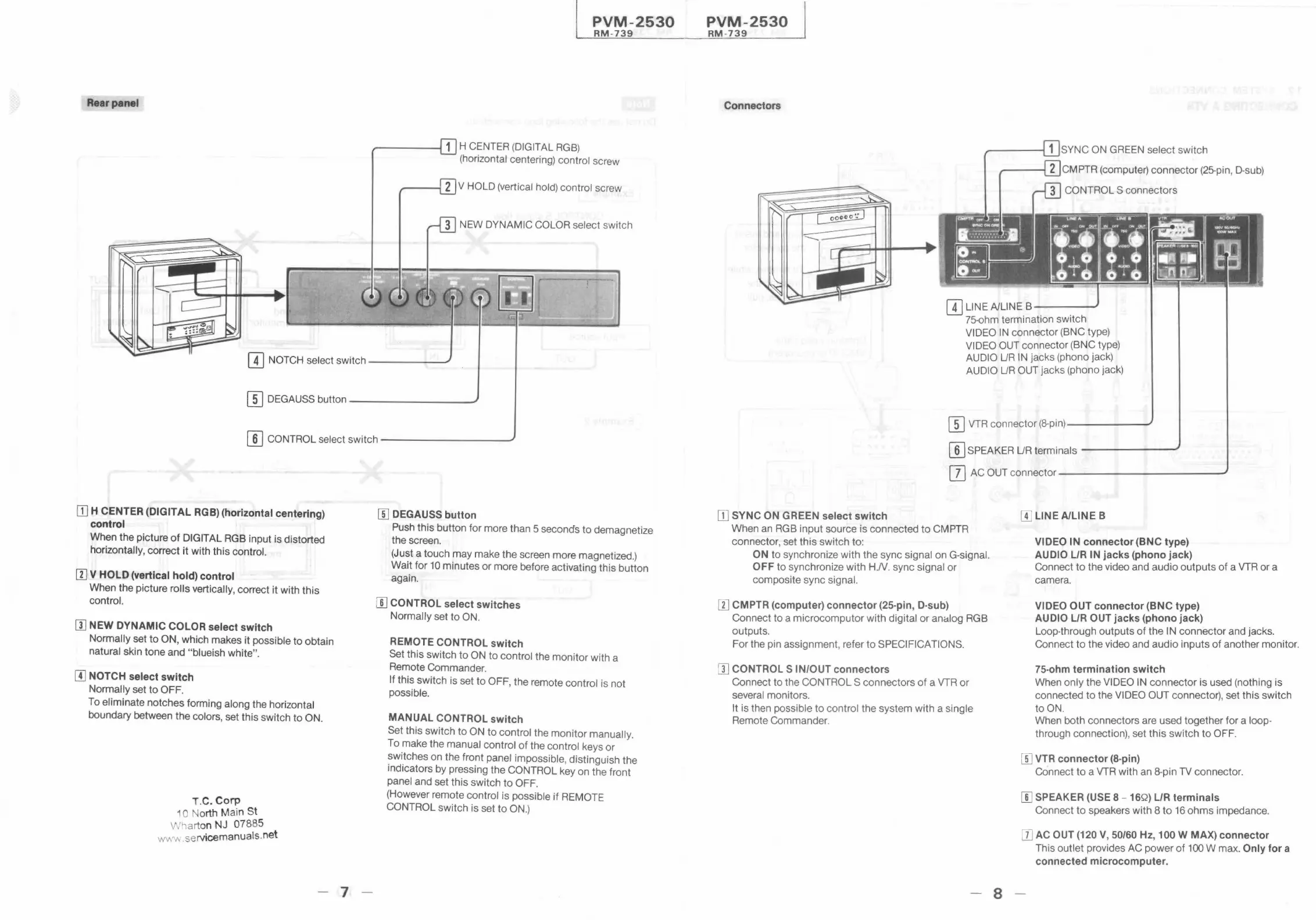
Rear panel
PVM-2530
RM -739
~----1 1 H CENTER (DIGITAL RGB)
(horizontal centering) control screw
-----ii 2 V HOLD (vertical hold) control screw
IT] NOTCH select switch ----~ -
(I] DEGAUSS button_ .......,_.._. _____ _
(]] CONTROL select switch------ ----
[TI H CENTER (DIGITAL RGB) (horizontal centering)
control
When the picture of DIGIT AL RGB input is distorted
horizontally, correct it with this control.
[I] V HOLD (vertical hold) control
When the picture rolls vertically, correct it with this
control.
[I] NEW DYNAMIC COLOR select switch
Normally set to ON, which makes it possible to obtain
natural skin tone and "blueish white".
[I] NOTCH select switch
Normally set to OFF.
To eliminate notches forming along the horizontal
boundary between the colors, set this switch to ON.
T.C. Corp
1 o North Main St
Wharton NJ 07885
wv.v. .servicemanuals.net
- 7
W DEGAUSS button
Push this button for more than 5 seconds to demagnetize
the screen.
(Just a touch may make the screen more magnetized.)
Wait for 10 minutes or more before activating this button
again.
[[] CONTROL select switches
Normally set to ON.
REMOTE CONTROL switch
Set this switch to ON to control the monitor with a
Remote Commander.
If this switch is set to OFF, the remote control is not
possible.
MANUAL CONTROL switch
Set this switch to ON to control the monitor manually.
To make the manual control of the control keys or
switches on the front panel impossible , distinguish the
indicators by pressing the CONTROL key on the front
panel and set this switch to OFF.
(However remote control is possible if REMOTE
CONTROL switch is set to ON.)
PVM-2530
RM-739
Connectors
SYNC ON GREEN select switch
CMPTR (computer) connector (25-pin, D-sub)
CONTROLS connectors
[I) LINE A/LINE B-- --
75-ohm termination switch
VIDEO IN connector (BNC type)
VIDEO OUT connector (BNC type)
AUDIO UR IN jacks (phono jack)
AUDIO UR OUT jacks (phono jack)
(]] VTR connector (8-pin)-------
[I) SPEAKER UR terminals -- -----
[]] AC OUT connector- ------ -- - ---
[I] SYNC ON GREEN select switch
When an RGB input source is connected to CMPTR
connector, set this switch to:
ON to synchronize with the sync signal on G-signal.
OFF to synchronize with H.N . sync signal or
composite sync signal.
[I] CMPTR (computer) connector (25-pin, D-sub)
Connect to a microcomputor with digital or analog RGB
outputs.
For the pin assignment , refer to SPECIFICATIONS.
[I] CONTROLS IN/OUT connectors
Connect to the CONTROLS connectors of a VTR or
several monitors.
It is then possible to control the system with a single
Remote Commander.
- 8
[I] LINE A/LINE B
VIDEO l'N connector (BNC type)
AU DIO L/R IN jacks (phono jack)
Connect to the video and audio outputs of a VTR or a
camera.
VIDEO OUT connector (BNC type)
AUDIO L/R OUT jacks (phono jack)
Loop-through outputs of the IN connector and jacks.
Connect to the video and audio inputs of another monitor.
75-ohm termination switch
When only the VIDEO IN connector is used (nothing is
connected to the VIDEO OUT connector), set this switch
to ON.
When both connectors are used together for a loop-
through connection), set this switch to OFF.
W VTR connector (8-pin)
Connect to a VTR with an 8-pin TV connector.
[[] SPEAKER (USE 8 - 16Q) L/R terminals
Connect to speakers with 8 to 16 ohms impedance.
DJ AC OUT (120 V, 50/60 Hz, 100 W MAX) connector
This outlet provides AC power of 100 W max. Only for a
connected microcomputer.