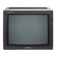
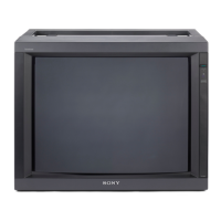
PVM-2530
RM-739
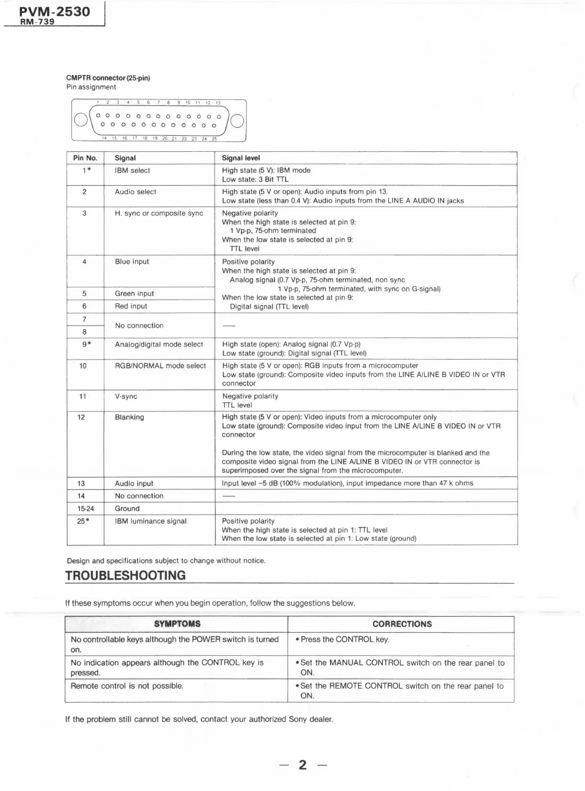
CM PTR connector (25-pin)
Pin assignment
0
1 2 3 4 5 6 7 8 9 10 11 12 13
0 0 0 0 0 0 0 0 0 0 0 O 0
0 0 0 0 0 0 0 0 0 0 0 O
14 15 16 17 18 19 20 21 22 23 24 25
Pin No.
Signal
1*
IBM select
2
Audio select
3
H. sync or composite sync
4 Blue input
5 Green input
6
Red input
7
No connection
8
9*
Analog/digital mode select
10
RGB/NORMAL mode select
11 V-sync
12 Blanking
13 Audio input
14
No connection
15-24 Ground
25*
IBM luminance signal
0
Signal level
High state (5 V): IBM mode
Low state: 3 Bit TTL
High state (5 V or open): Audio inputs from pin 13.
Low state (less than 0.4 V): Audio inputs from the LINE A AUDIO IN jacks
Negative polarity
When the high state is selected at pin 9:
1 Vp-p, 75-ohm terminated
When the low state is selected at pin 9:
TTL level
Positive polarity
When the high state is selected at pin 9:
Analog signal (0.7 Vp-p, 75-ohm terminated, non sync
1 Vp-p, 75-ohm terminated, with sync on G-signal)
When the low state is selected at pin 9:
Digital signal (TTL level)
-
High state (open): Analog signal (0.7 Vp-p)
Low state (ground): Digital signal (TTL level)
High state (5 V or open): RGB inputs from a microcomputer
Low state (ground): Composite video inputs from the LINE A/LINE B VIDEO IN or VTR
connector
Negative polarity
TTL level
High state (5 V or open): Video inputs from a microcomputer only
Low state (ground): Composite video input from the LINE A/LINE B VIDEO IN or VTR
connector
During the low state, the video signal from the microcomputer is blanked and the
composite video signal from the LINE A/LINE B VIDEO IN or VTR connector is
superimposed over the signal from the microcomputer .
Input level -5 dB (100% modulation), input impedance more than 47 k ohms
-
Positive polarity
When the high state is selected at pin 1: TTL level
When the low state is selected at pin 1: Low state (ground)
Design and specifications subject to change without notice.
TROUBLESHOOTING
If these symptoms occur when you begin operation, follow the suggestions below.
SYMPTOMS
CORRECTIONS
No controllable keys although the POWER switch is turned
• Press the CONTROL key.
on.
No indication appears although the CONTROL key is
• Set the MANUAL CONTROL switch on the rear panel to
pressed.
ON.
Remote control is not possible. • Set the REMOTE CONTROL switch on the rear panel to
ON.
If the problem still cannot be solved, contact your authorized Sony dealer.
2