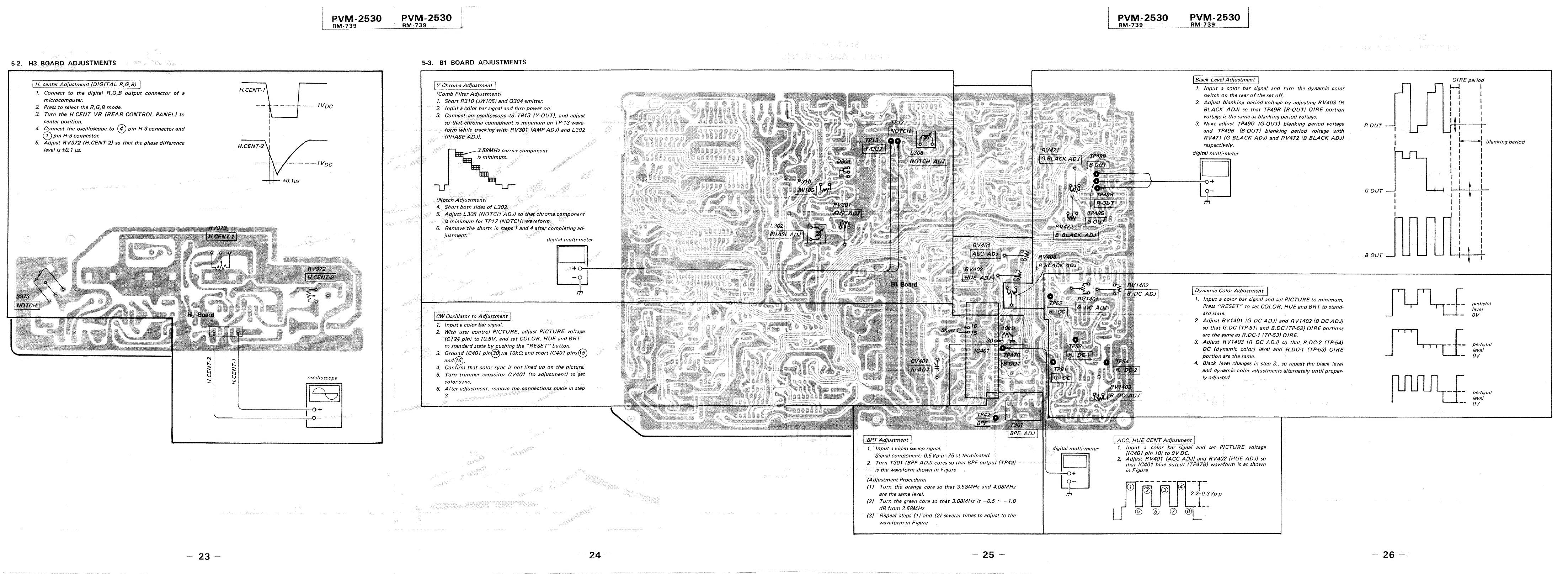
5-2. H3 BOARD ADJUSTMENTS
! H. center Adjustment (DIGITAL R,G,B)
1. Connect to the digitaf R,G,B output connector of a
microcomputer.
2 Press to select the R,G,B mode.
3_ Turn the H.CENT VR /REAR CONTROL PANEL} to
center position.
4. Connect the oscilloscope to © pin H-3 connector and
(j) pin H-3 connector.
5. Adjust R V972 (H.CENT-2) so that the phase difference
level is ±0. 1 µs.
23
PVM-2530
RM-739
IVDc
H_CENT-2
----tvoc
±0. 1 µ.s
oscilloscope
l°c
7
I
~-------~--o+
PVM-2530
RM-739
5-3. Bl BOARD ADJUSTMENTS
! Y Chroma Adjustment I
(Comb Filter Adjustment)
1. Short R310 (JW105J and 0304 emitter.
2. Input a color bar signal and turn power on.
3. Connect ,E!n oscilloscope to TP13 (Y-OUTJ, and adjust
so that chroma compOnent is minimum on TP-13 wave-
fofm while tracking with RV301 (AMPAOJ) and L302
/PHASE ADJ).
-~~3.58MHz carrier component
is minimum.
/Notch Adjustmen-'i:)
4. Short both sides of L302..
5. Adjust L308 (NOTCH ADJ) so that chroma component
is minimum for TP17 (NOTCH) waveform,
6. Remove the shorts in stfJps' 1 and 4 a(ter completing ad-
justment
digital multi·meter
I CW Oscillator to Adjustment j
1. Input a color bar signal.
2 With user control PICTURE, adjust PICTURE voltage
(Ct 24 pin/ to 10.5V, and set COLOR, HUE and BRT
to standard state by pushing the "RESET"' button.
3, Ground JC401 pin@v1a 10ki1 and short IC401 pins@
and@. _ . .
4. Confirm that color sync Is not !med up on the p1cturf!,
5. Turn trimmer capacitor CV401 (to adjustment) to !}et
color sync.
6. After adjustment, remove the connections made in step
3.
24 -
1. Input a video sweep s1'.gnal.
Signal comPonent: 0.5Vp-p: 15 .11 terminated.
2. Turn T301 (SPF ADJ) cores so that BPF output (TP42J
is the waveform shown in Figure
(Adjustment Procedure)
(1) Turn the orange core so that 3.58MHz and 4.08MHz
are the same level.
(2) Turn the green core so that 3.08MHz is -0.5 - -1.0
dB from 3.58MHz.
(3) Repeat steps (1) tmd (2) several times to adjust to the
waveform in Figure
- 25 -
di'gitai multi"meter
ijJ
PVM-2530
RM-739
PVM-2530
RM-739
I Black Level Adjustment I
1. Input a color bar signal and turn the dynamic color
switch on the rear of the set off.
2 Adjust blanking period voltage by adjusting R V403 (R
BLACK ADJ) so that TP49R (R~OUTJ O!RE portion
voltage is the same as blanking period voltage.
3. Next adjust TP49G (G-OUT) blanking period voltage
and TP49B (B-OUT) blanking period voltage with
RV471 (G BLACK ADJ) and RV472 /B BLACK ADJ)
respectively.
digital multi-meter
[ovf]a"mic Color Adjustment 1
1. Input a color ba( signal and set PICTURE to minimum.
Press "RESET" to set COLOR, HUE and BRT to stand-
ard state.
2. Adjust RV/401 /G DC ADJ) and RV/402 (B DC ADJ)
so that G.DC (TP-51) and B.DC (TP-52) DIRE portions
are the same as R.DC·1 (TP-53) 0/RE.
3, Adjust RV1403 (R DC ADJ) so that R.DC-2 (TP·54)
DC (dynamic color} level and R.DC-1 (TP-53} OIRE
portion are the same.
4, Black level changes in step 3., so repeat the black level
and dynamic color adjustments alternately until proper-
ly adjus(ed.
I ACC, HUE CENT Adjustment I
1. Input a color bar ,;ignal and set PICTURE voltage
/IC401 pin 18) to 9V DC_
2. Adjust RV401 (ACC ADJ) and RV402 {HUE ADJ) so
that IC401 blue output (TP41B) waveform is as shown
in Figure
0
®
®
®
--r-
_4 i
2.210.3Vp-p
I
1 __
0 @
ROUT
GOUT
BOUT
- 26 -
GIRE period
1-.J I
I
I
I
I
I
I
I
I
I, I
1
•1 blanking period
I
I
I
I
I
! I
pedistal
level
ov
ped!sta/
level
ov
pedistal
level
OV
 Loading...