– 22 –
KV-B14PD1
RM-883
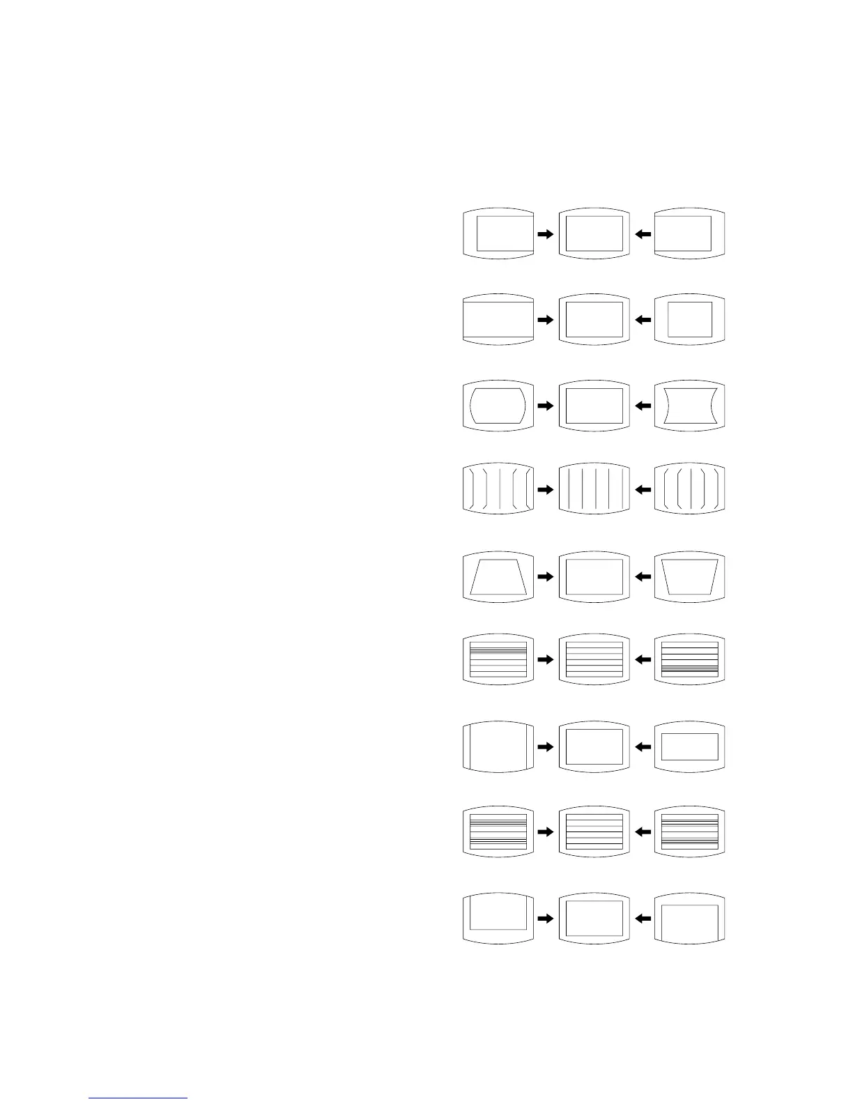
5-4. PICTURE DISTORTION ADJUSTMENT
Item Number 00 – 08
00 HSF (H SHIFT)
01 HSZ (H SIZE)
02 PAP (PIN AMP)
03 CNP (CORNER PIN)
04 TLT (TILT)
05 VSL (V SLOP)
06 VAP (V ANP)
07 SCR (S CORRECTION)
08 VSF (V SHIFT)
00 HSF (H SHIFT)
01 HSZ (H SIZE)
02 PAP (PIN AMPLITUDE)
03 CNP (CORNER PIN)
04 TLT (TILT)
05 VSL (V SLOPE)
06 VAP (V AMPLITUDE)
07 SCR (S CORRECTION)
08 VSF (V SHIFT)
5-3. A BOARD ADJUSTMENT AFTER IC003
(MEMORY) REPLACEMENT
1. Enter to Service Mode.
2. Press commander buttons [5] and [0] (Data Initialize), and [2]
and [0] (Data Copy) to initialize the data.
3. Call each item number, and check if the respective screen shows
the normal picture.
In case some items are not well-adjusted, give them fine
adjustment.
Write the data for each item number ([MUTING] + [0]).
4. Select item numbers “31” (OP0), “32” (OP1) and “33” (OP2)
and set the bit with command buttons [3] and [6].
5. Press commander buttons [8] and [0] (Test Normal) to return
all user adjustments to the data that was set on shipment from
the factory.
(= Cancel Service Mode).