7
For a target camera other than an ILME-FR7,
the IRIS, GAIN, and SHUTTER button
operations are enabled when the buttons
are lit blue.
For details about functions that can be
a
ssigned to the ASSIGN 4 to ASSIGN 6
buttons and how to assign the functions, see
“Assigning Functions to Assign Buttons”
(page 51).
For details about operation, see “Setting
Specific Functions using Shortcuts
(excluding ILME-FR7)” (page 59)or “Setting
Specific Functions using Shortcuts (ILME-
FR7)” (page 60).
For an ILME-FR7 target camera, the setup
ite
ms and values for some functions are
displayed overlaid on the camera image and
not on the LCD of the unit.
LCD panel
Displays the RM menu, FUNCTION menu,
an
d preset memory numbers.
• For details about menu operations, see
“Menu Operations” (page 12).
• For details about the RM menu, see “RM
Menu List” (page 68).
• For details about the FUNCTION menu, see
“Setting Specific Functions using Shortcuts
(excluding ILME-FR7)” (page 59) or “Setting
Specific Functions using Shortcuts (ILME-
FR7)” (page 60).
• For details about preset numbers, see
“Storing the Camera Status (Preset
Function)” (page 45).
SELECT knob and button
Use to select menu items.
For details about menu operations, see
“Menu Operations” (page 12).
VALUE knob and button
Use to select the settings of menu items.
For details about menu operations, see
“Menu Operations” (page 12).
CANCEL button
Use to move from a lower level to a higher
le
vel in the hierarchy for menu items that
have a multi-level hierarchy.
RM MENU button
Press this button to display the setup menu
of the
unit on the LCD panel.
For details about menu operations, see
“Menu Operations” (page 12).
CAM MENU button
Press and hold this button to display the
se
tup menu of the camera on the monitor
output of the camera. Nothing is displayed
on the LCD panel of the unit.
For details about operation, see “Operating
the Camera Setup Menu from the Unit
(Camera Menu Operation Mode) (excluding
ILME-FR7)” (page 48)or “Operating with the
Screen Display Overlaid
on the Camera
Image (CAM GUI Operation Mode) (ILME-
FR7)” (page 50).
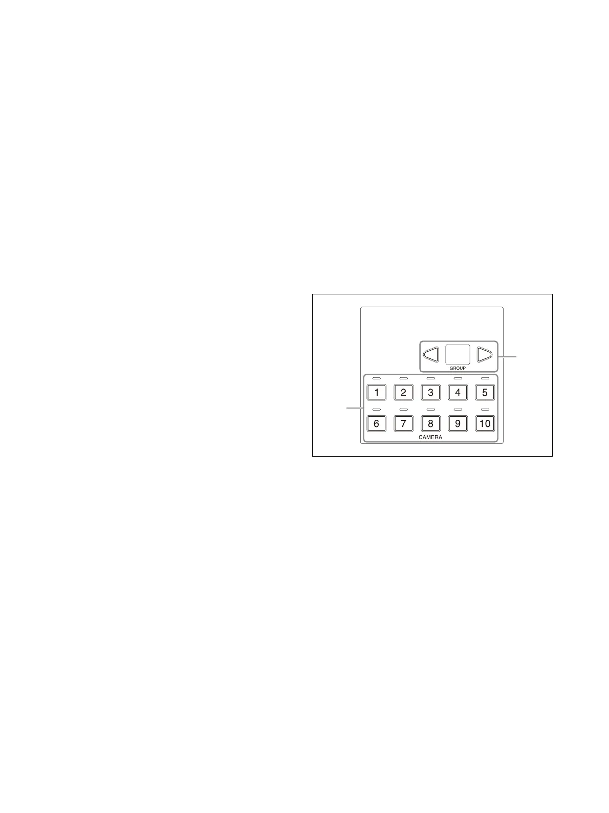
Camera selection block
Use to select the target camera to control.
When using LAN connection, the unit can control
u
p to 100 cameras.
When using serial connection, the unit can
control
up to 7 cameras.
CAMERA 1 to CAMERA 10 buttons, CAMERA
1
to CAMERA 10 tally input lamps
Selects the target camera from within a
gr
oup.
For details about selecting the target
ca
mera, see “Selecting a Camera” (page 34).
When a camera selected by an external
d
evice, such as a switcher, is outputting a
tally signal, the tally input lamp on the top of
the corresponding camera button lights up.
For details about tally input lamps, see
“About the tally input lamp
indicators”
(page 34).
GROUP LEFT button, group number
d
isplay, GROUP RIGHT button
Select the target camera group using the
GR
OUP LEFT button and GROUP RIGHT
button. The number of the selected group is
displayed in the group number display.
Group numbers are used with LAN
c
onnections.