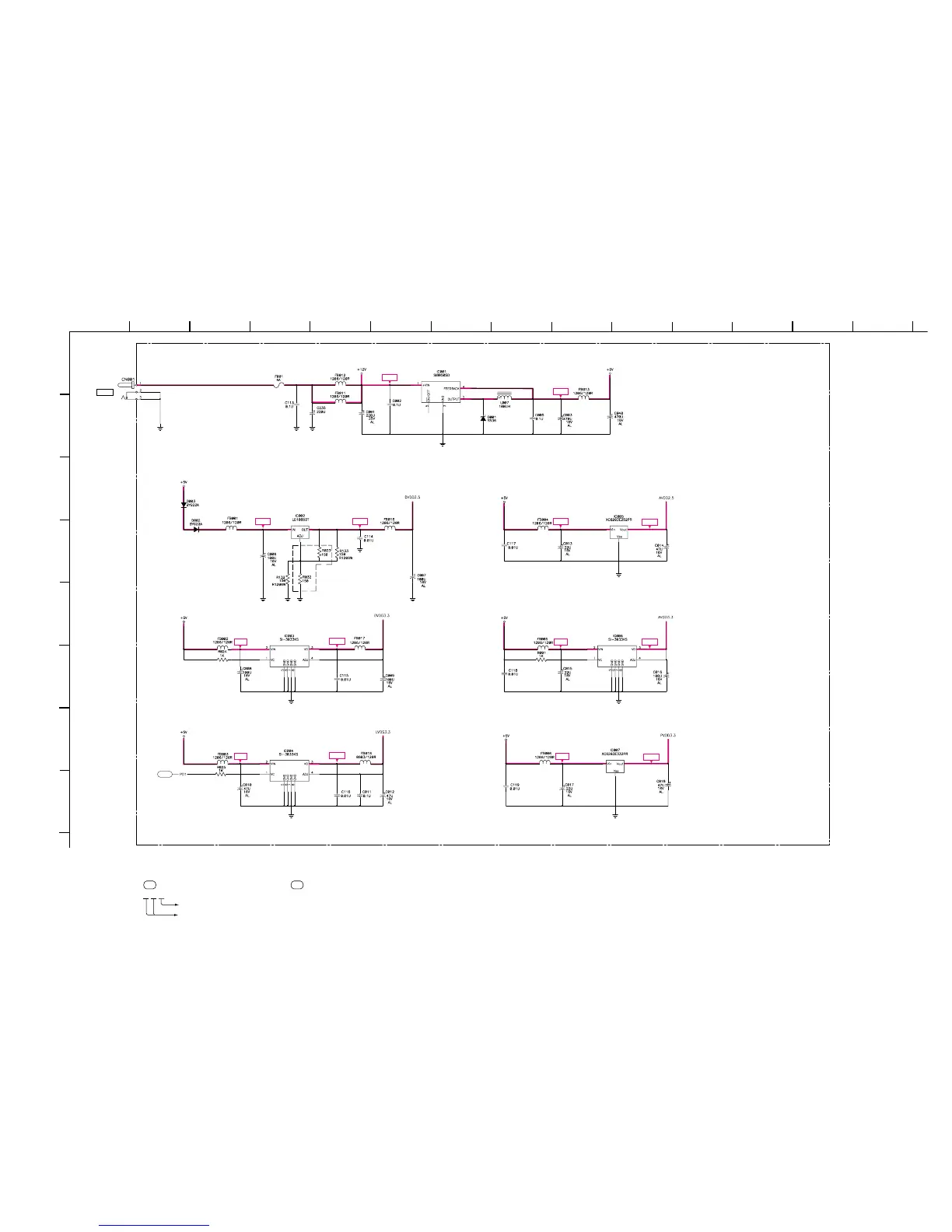
SDM-S71 (E) 3-6
(2) Schematic Diagram of INTERFACE (
aa
aa
a,
bb
bb
b,
cc
cc
c,
dd
dd
d,
ee
ee
e,
ff
ff
f) Board
1
A
B
C
D
E
F
G
H
2
12
13
11
10
98765
43
14
+12V
+5V
+5V +2.5V +5V
+2.5V
+5V
+3.3V
+5V
+3.3V
+5V
+3.3V
+5V
+3.3V
INTERFACE-a
(POWER)
B-SS3628<J..> - INTERFACE-P1
+5V REG
+2.5V REG
+3.3V REG
+3.3V REG
af1
DC12V
+2.5V REG
+3.3V REG
+3.3V REG
• Divided circuit diagram
One sheet of INTERFACE board circuit diagram is divided into six sheets,
each having the code INTERFACE-a to INTERFACE-f. For example, the destination
ab1 on the code INTERFACE-a sheet is connected to ab1 on the INTERFACE-b sheet.
a b 1
Ref. No.
Circuit diagram division code