6-2
2-1-6. Adjusting Sequence
Make the electrical adjustment in the following sequence.
Checking power supply
Servo system adjustment
Audio system adjustment
2-3. SERVO SYSTEM ADJUSTMENTS
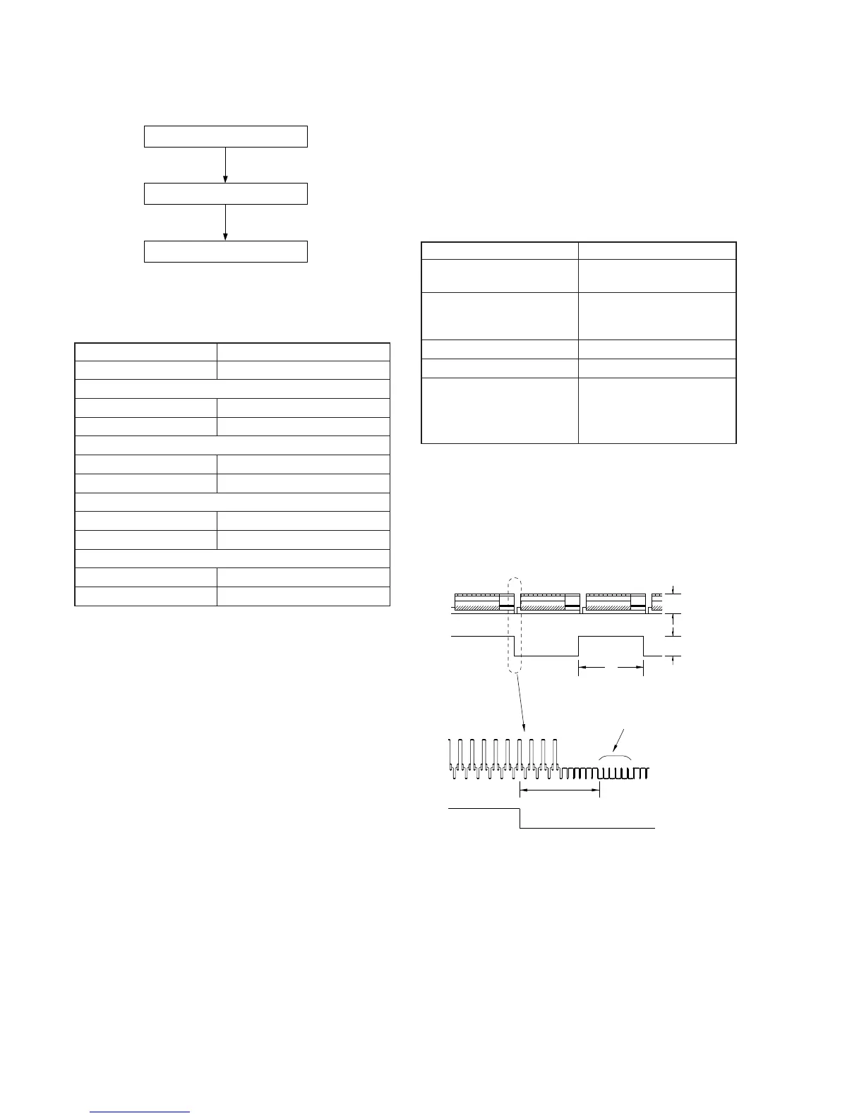
2-3-1. RF Switching Position Adjustment
(MA-366 Board)
Purpose:
Adjust the interval between A ch and B ch of tape playback out-
put.
Improve the interchangeability with other tapes and sets.
When it is out of order, the interval appears on the screen, the
screen is disturbed.
Mode PB
Signal Alignment tape SP mode
color bar
Measurement Point CH1: VIDEO LINE OUT
CH2: Pin 3 of CN202
(V SWP)
Measuring Instrument Oscilloscope
Adjusting Element RV101
Specified Value 6.5 ± 1.0 H (416 ± 60 µsec)
PAL
6.5 ± 1.0 H (413 ± 60 µsec)
NTSC
Adjusting Method:
1) Connect MA-366 board JS401 to the GND for about 1 second
to activate the RF switching position adjustment mode.
2) Check that D403 and D405 mutually flash on and off quickly.
3) Check that switching position is 6.5 ± 1.0 H.
4) If not meet the specified value, turn RV101 and repeat steps 3
to 4.
Fig. 6-2-3.
Mode E-E
Measuring Instrument Digital voltmeter
+12 V check
Measurement Point Collector of Q604
Specified Value 12.0 ± 0.3 V
+5 V check
Measurement Point Pin 7 of CN001
Specified Value 5.0 ± 0.25 V
+9 V check
Measurement Point Emitter of Q604
Specified Value 9.0 ± 0.3 V
MTR12 V check
Measurement Point Pin 4 of CN001
Specified Value 12.0 ± 0.3 V
2-2. POWER SUPPLY ADJUSTMENTS
2-2-1. Power Supply Check
(MA-366 Board)
Checking Method:
1) Confirm that each voltage meets its specified value.
Approx. 1 Vp-p
Approx. 5 Vp-p
V
enargement
CH2
CH1
CH2
CH1
Vertical sync. signal
6.5 ± 1.0 H
(416 ± 60 µsec) PAL
(413 ± 60 µsec) NTSC