6-3 6-4 E
2-4. AUDIO SYSTEM ADJUSTMENTS
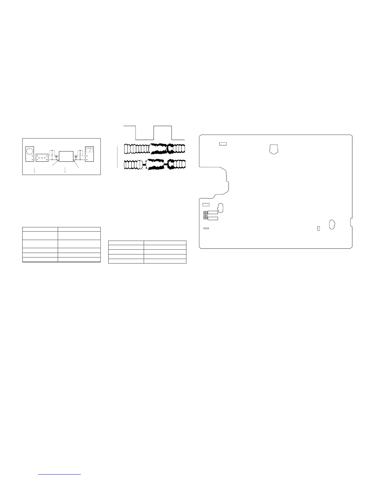
• Adjust both Lch and Rch.
[Connection]
Fig. 6-2-4.
2-4-1. Hi-Fi Audio System Adjustment
(SLV-GF85/SP100)
• Set switches and knobs to the following positions to make ad-
justment unless otherwise specified.
AUDIO MONITOR.......................... STEREO
1. AF Switching Position Adjustment (MA-366 Board)
Purpose:
Adjust the interval between A ch and B ch of tape playback out-
put. Improve the interchangeability with other tapes and sets.
When it is out of order, noisy sound is increased and big noise is
heard.
Mode PB
Signal Alignment tape SP mode color
bar
Measurement point CH1: Pin 3 of CN202
CH2: Pin 1 of CN202
Measuring Instrument Oscilloscope
Adjusting Element RV102
Specified Value Fig. 6-2-5
Adjusting Method:
1) Connect MA-366 board JS401 to the GND for about 1 second
to activate the RF switching position adjustment mode.
2) Check that D403 and D405 mutually flash on and off quickly.
3) Adjust RV102 to minimize a chipped portion.
At the time, confirm that a noisy sound is not heard.
Audio
generator
Attenuator
600 Ω
47 kΩ
VCR
Audio level meter or
distortion meter
AUDIO LINE OUT
AUDIO LINE IN
Feed signal both
channelssimultaneously.
CH2
CH1
RF SWP
OK
NG
Fig. 6-2-5.
2-4-2. Normal Audio System Adjustment
• Make adjustment in the SP mode, unless otherwise specified.
Use a normal VHS cassette for an adjustment tape.
• Set AUDIO MONITOR to normal.
[Adjustment Sequence]
1. ACE Head Adjustment
2. E-E Output Level Check
1. ACE Head Adjustment
Refer to the service manual of VHS MECHANICAL
ADJUSTMENT VI.
2. E-E Output Level Check
Purpose:
Confirm that the output level against the reference input is within
the specification.
Mode E-E
Signal L, R: 400 Hz, –7.5 dBs
Measurement point Audio output terminal
Measurement equipment Audio level meter
Specified value –7.5 ± 2 dBs
Confirmation Method:
1) Simultaneously input a signal of 400 Hz, –7.5 dBs to both L
and R channels of Audio Line Input.
2) Confirm that the audio output level is –7.5 ± 2 dBs.
2-5. PARTS ARRANGEMENT DIAGRAM FOR ADJUSTMENTS
MA-366 BOARD (side A)
Q604
E
C
B
CN001
17
CN202
41
RV101
RF SWP
RV102
AF SWP
JS401