7-2
Mode E-E
Measuring Instrument Digital voltmeter
–11.5 V check
Measurement Point Pin 8 of CN600
(MA-314 board)
Specified Value 11.4 V
D6 V check
Measurement Point Pin 7 of CN600
(MA-314 board)
Specified Value 5.9 ± 0.2 V
+13 V check
Measurement Point Pin 2, 3 of CN600
(MA-314 board)
Specified Value 13.75 ± 0.55 V
+35 V check
Measurement Point Pin 1 of CN600
(MA-314 board)
Specified Value 35 ± 3.5 V
2-2. POWER SUPPLY ADJUSTMENT
2-2-1. Power Supply Check
Checking Method:
1) Confirm that each voltage meets its specified value.
Checking power supply
Video system
adjustment
Servo system adjustment
Audio system
adjustment
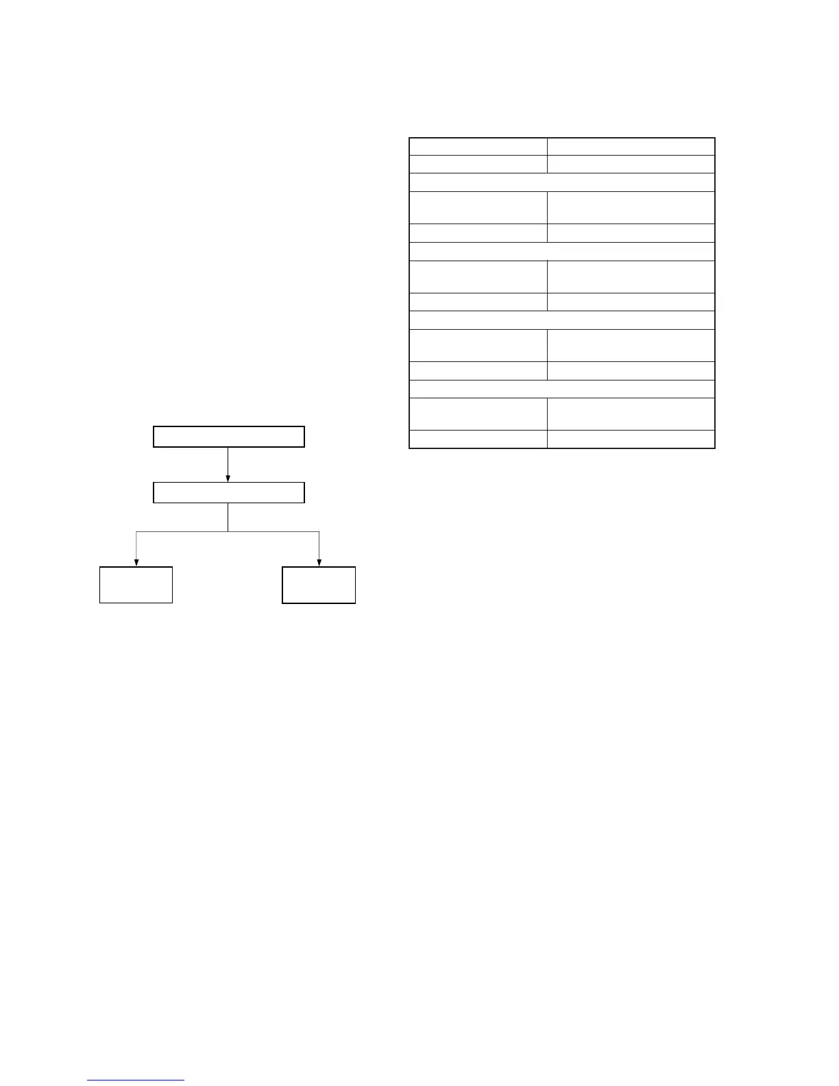
2-1-5. Specified I/O Level and Impedance
Input/output terminal
Video inputs LINE IN : phono jacks
EURO-AV : 21-pin (Pin @º) 1 Vp-p, 75 Ω,
unbalanced, sync nagative
Audio inputs LINE IN : phono jack
47 kW, –75 dBs (0 dBs = 0.775 Vrms)
EURO-AV : 21-pin (Pin 2 and 6)
More than 10 kΩ, –4 dBs
Video outputs LINE OUT : phono jack
EURO-AV : 21-pin (Pin !ª) 1 Vp-p, 75 Ω,
unbalanced, sync negative
Audio outputs LINE OUT : phono jacks
–7.5 dBs at load
impedance 47 kΩ
Output impedance : less than 10 kΩ
EURO-AV : 21-pin (Pin 1 and 3)
Output impedance : less than 1 kΩ
–4 dBs with 10 kΩ load
2-1-6. Adjusting Sequence
Make the electrical adjustment in the following sequence.
+1.2
–0.5