– 46 –
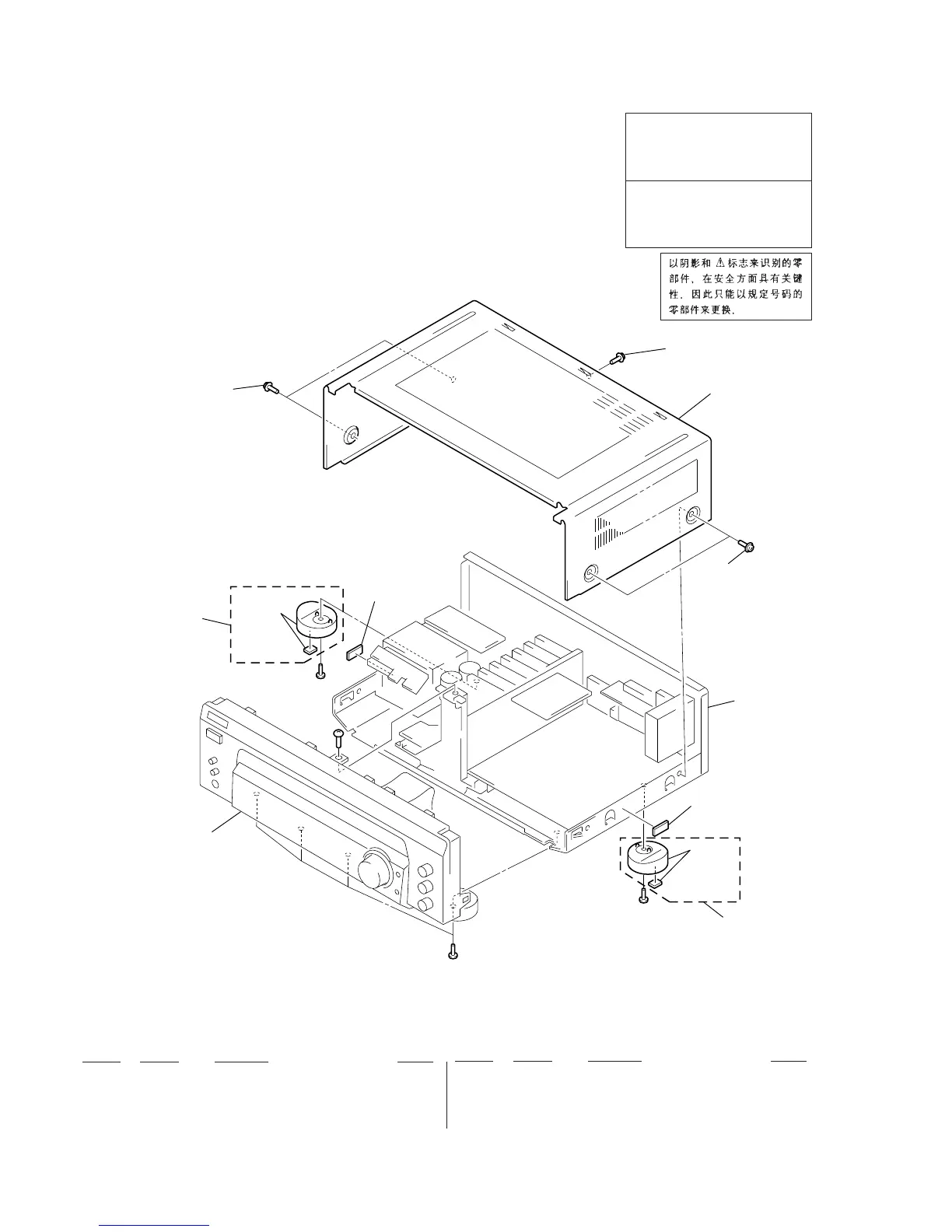
(1) CASE SECTION
SECTION 6
EXPLODED VIEWS
Les composants identifiés par une
marque ! sont critiquens pour la
sécurité.
Ne les remplacer que par une pièce
portant le numéro spécifié.
The components identified by
mark ! or dotted line with mark
! are critical for safety.
Replace only with part number
specified.
• Items marked “*” are not stocked since they
are seldom required for routine service. Some
delay should be anticipated when ordering
these items.
• The mechanical parts with no reference num-
ber in the exploded views are not supplied.
• Hardware (# mark) list and accessories and
packing materials are given in the last of the
electrical parts list.
NOTE:
• -XX and -X mean standardized parts, so they
may have some difference from the original
one.
• Color Indication of Appearance Parts
Example:
KNOB, BALANCE (WHITE) . . . (RED)
↑↑
Parts Color Cabinet's Color
Ref. No. Part No. Description Remark
Ref. No. Part No. Description Remark
1 X-4947-207-1 FOOT ASSY (F50150S)
(DE335: AEP, E, MY, SP, AUS/V323)
1 X-4947-208-1 FOOT ASSY (F50150S)
(DE335: US, CND/SE391)
2 4-210-291-01 SCREW (CASE 3 TP2)
* 3 4-998-206-01 CASE (413226)
• Abbreviation
AUS : Australian model
CND : Canadian model
MY : Malaysia model
SP : Singapore model
2
2
3
2
1
1
#1
#1
#1
#1
Front panel
section
not supplied
not
supplied
not supplied
not
supplied
Chassis section