EasyManua.ls Logo

Sony STR-DE335 Service Manual

Sony STR-DE335
45 pages
To Next Page IconTo Next Page
Page #1 background imageLoading...
Page #1 background image
SERVICE MANUAL
FM STEREO/FM-AM RECEIVER
US Model
STR-DE335/SE391
Canadian Model
AEP Model
E Model
Australian Model
STR-DE335
Chinese Model
STR-V323
STR-DE335/SE391/V323
SPECIFICATIONS
Photo: STR-DE335 US model
Audio power specifications (US model)
POWER OUTPUT AND TOTAL HAR-
MONIC DISTORTION
With 8-ohm load, both channels driven,
from 20
a)
– 20,000 Hz, rated 100 watts
per channel minimum RMS power, with
no more than 0.09 %
b)
total harmonic
distortion from 250 milliwatts to rated
output.
STR-SE391:
a) 40Hz
b) 0.5 %
Amplifier section
Power output
Stereo mode STR-DE335/V323
US, Canadian models:
(8 ohms at 20 Hz – 20 kHz
less than 0.09 % total
harmonic distortion)
100 W + 100 W
AEP model:
(DIN 1 kHz, 4 ohms)
80 W + 80 W
Malaysia, Singapore,
Chinese, Australian
models:
Rated power:
(8 ohms at 1 kHz,
THD 0.7 %)
80 W + 80 W
Reference power:
(8 ohms at 20 Hz – 20 kHz,
less than 0.09 % total
harmonic distortion)
70 W + 70 W
E model:
Rated power: (8 ohms at
1kHz, THD 0.7 %)
100 W + 100 W
Reference power:
(8 ohms at 20 Hz – 20 kHz,
less than 0.09 % total
harmonic distortion)
95 W + 95 W
STR-SE391
(8 ohms at 40 Hz – 20 kHz,
less than 0.5 % total
harmonic distortion)
100 W + 100 W
Surround mode STR-DE335/V323
and 5.1 CH/DVD US, Canadian models:
mode (8 ohms at 1 kHz, THD
(Reference) 0.8%)
Front: 80 W/ch
Center: (Pro Logic mode)
80 W
Rear: 80 W/ch
AEP model:
(DIN 1 kHz, 4 ohms)
Front: 70 W/ch
Center: 70 W
(only in PRO LOGIC
mode)
Rear: 70 W/ch
E, Malaysia, Singapore,
Chinese, Australian
models:
Rated power: (8 ohms at
1 kHz, THD 0.7 %)
Front: 80 W/ch
Center: (Pro Logic mode)
80 W
Rear: 80 W/ch
– Continued on next page –
STR-SE391
(8 ohms at 1 kHz,
THD 0.5 %)
Front: 80 W/ch
Center: (Pro Logic mode)
80 W
Rear: 80 W/ch
Reference power:
(8 ohms 20 Hz – 20 kHz,
less than 0.09 % total
harmonic distortion)
Front: 70 W/ch
Center: (Pro Logic mode)
70 W
Rear: 70 W/ch
RMS power:
(8 ohms at 1 kHz,
THD 10 %)
Front: 100 W/ch
Center: (Pro Logic mode)
100 W
Rear: 100 W/ch
Frequency PHONO: RIAA
response equalization curve ±0.5 dB
(STR-SE391)
TV/SAT (TV/LD), CD,
MD/TAPE, VIDEO
5.1 CH/DVD:
10 Hz – 50 kHz ± 1 dB
Ver 1.1 2001.07
9-928-870-12 Sony Corporation
2001G0500-1 Home Audio Company
C 2001.7 Shinagawa Tec Service Manual Production Group

Other manuals for Sony STR-DE335

Question and Answer IconNeed help?

Do you have a question about the Sony STR-DE335 and is the answer not in the manual?

Sony STR-DE335 Specifications

General IconGeneral
Impedance8 ohms
Total Harmonic Distortion0.09%
Speaker Load Impedance8 ohms
Power Output100W per channel (8 ohms, 20Hz-20kHz, 0.09% THD)
Frequency Response10 Hz - 50 kHz +0/-3 dB
Inputsphono, cd, tape, video
Outputstape, video
Tuning RangeFM, AM
Input Sensitivity2.5mV (MM), 200mV (line)
Signal to Noise Ratio80dB (phono)
Dimensions430 x 145 x mm
Channel Separation50dB

Summary

Service Manual Introduction

Model Identification

Lists the different model numbers and their regional variations for service.

Power Specifications Overview

Details power output and harmonic distortion across models and modes.

General Specifications

Covers frequency response and other technical performance parameters.

Servicing and Safety Precautions

Servicing Notes and Safety Check-out

General service guidelines and post-repair safety checks.

AC Leakage Test Procedure

Method for testing AC leakage current to ensure safety compliance.

Front Panel Controls and Indicators

Front View Control Layout

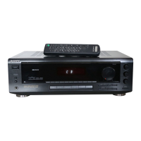
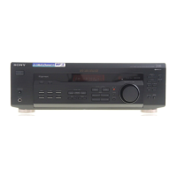
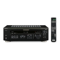
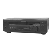
Identifies all buttons, knobs, and jacks on the front panel.

Rear Panel Connections

Rear Panel Connector Layout

Diagrams and labels for rear panel connections across different models.

Disassembly Procedures

Case and Front Panel Removal

Step-by-step instructions for removing the outer case and front panel assembly.

Test Modes and Diagnostics

Test Mode Procedures

Guides for initialization, display test, AM tuning interval selection, and software version display.

Block Diagrams - Main Section

MAIN Section Block Diagram (1/2)

Illustrates the signal flow and major component blocks of the main section's audio path.

Diagram Interpretation Notes

Notes on Schematic Diagrams

Explains symbols, notations, tolerances, and signal paths for diagrams.

Waveform Examples

Illustrates typical waveforms at key ICs for troubleshooting.

Circuit Board Locations

Internal Circuit Board Layout

Visual guide showing the physical placement of all internal circuit boards.

Printed Wiring Diagrams - Main Board

MAIN Board Component Layout

Detailed layout of the MAIN board showing component placement and PCB traces.

Schematic Diagrams - Main & Rear Amp Boards

MAIN (1/4) & REAR AMP Board Schematics

Circuit diagrams for parts of the MAIN and REAR AMP boards.

IC Block Diagrams - Main Board

IC Block Diagrams for Main Board

Internal functional block diagrams for key ICs on the main board.

IC Pin Function Descriptions - Display Board

IC201 (System Controller) Pin Functions

Detailed pinout and function description for the system controller IC.

Exploded Views - Case Section

Case Section Assembly Diagram

Exploded view illustrating the assembly of the outer case and its parts.

Exploded Views - Front Panel Section

Front Panel Assembly Diagram

Exploded view detailing the front panel assembly and its constituent parts.

Exploded Views - Part Identification

Chassis Section Parts List

Lists part numbers for chassis components, cross-referenced by model.

Electrical Parts List - Display Board

Display Board Components

Comprehensive list of components for the display board (ICs, capacitors, resistors, etc.).

Revision History

Revision Log

Records updates and corrections made to the service manual over time.