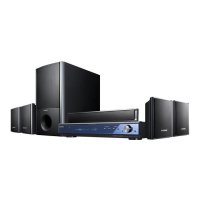
STR-KS360/KS360S
4
SECTION 2
GENERAL
This section is extracted
from instruction manual.
Description and location of parts
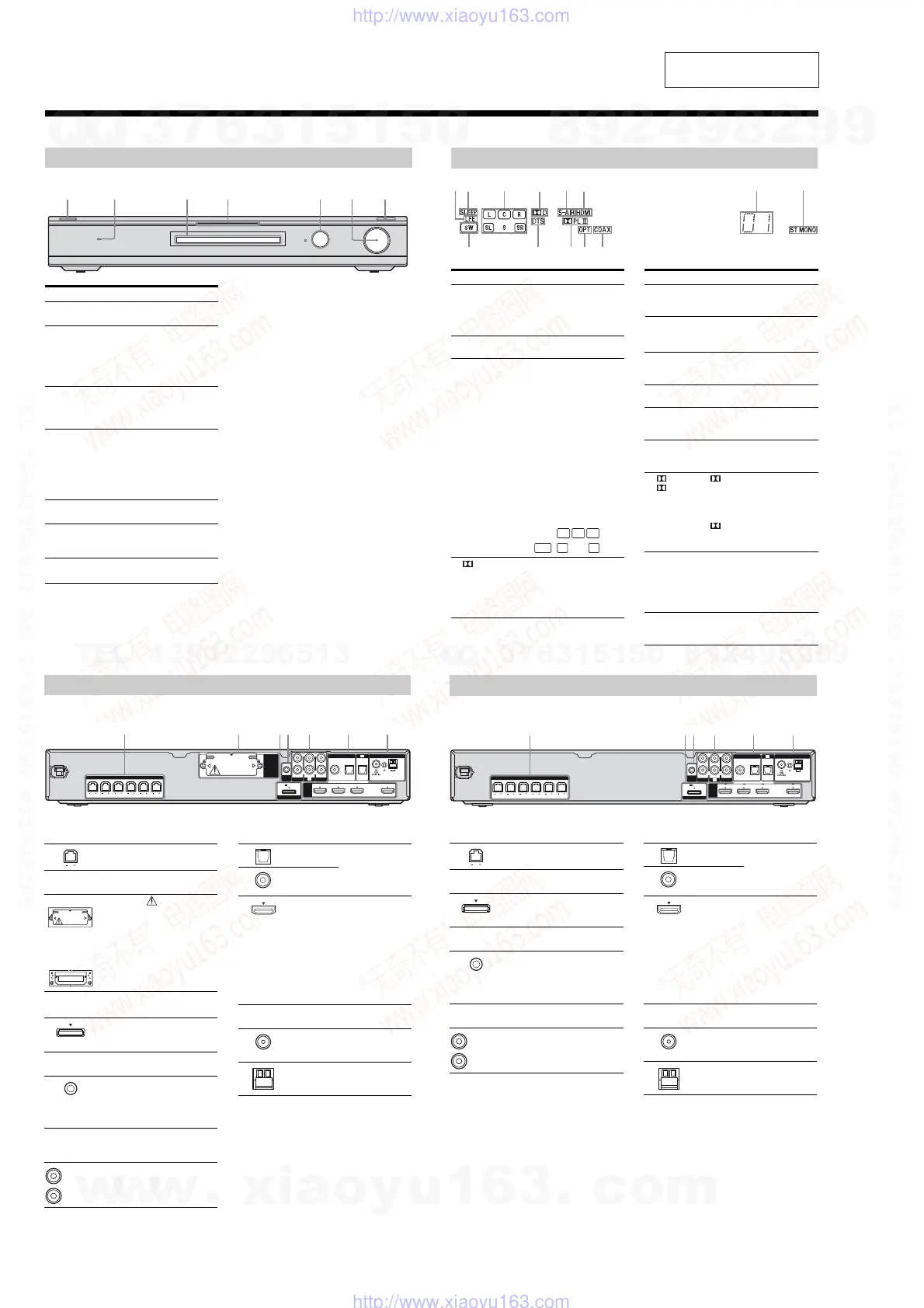
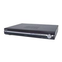
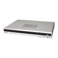
Front panel
ACTIVE STANDBY
INPUT SELECTOR
MASTER VOLUME
Name Function
" /
(on/standby)
Press to turn the receiver
on or off.
# ACTIVE
STANDBY
lamp
Lights up in amber when
the Control for HDMI
and/or S-AIR standby
mode are set to on and the
receiver is on standby
mode.
$ Display The current status of the
selected component or a
list of selectable items
appears here.
% White lamp Lights up when the
receiver is on and DSPL is
settooninDISPLAY
function. Lights off when
the receiver is in standby
mode or DSPL is set to
off in DISPLAY function.
& Remote sensor Receives signals from
remote commander.
' MASTER
VOLUME
Turn to adjust the volume
level of all speakers at the
same time.
( INPUT
SELECTOR
Press to select the input
source to playback.
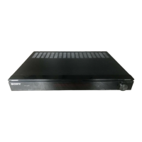
Indicators on the display
RRBRTRE
Name Function
" LFE Lights up when the disc being
played back contains an LFE
(Low Frequency Effect) channel
and the LFE channel signal is
actually being reproduced.
# SLEEP Lights up when the sleep timer is
activated.
$ Playback
channel
indicators
L
R
C
SL
SR
S
Theletters(L,C,R,etc.)indicate
the channels being played back.
The boxes around the letters vary
to show how the receiver
downmixes the source sound.
Front Left
Front Right
Center (monaural)
Surround Left
Surround Right
Surround (monaural or the
surround components obtained
by Pro Logic processing)
Example:
Recording format (Front/
Surround): 3/2.1
Sound Field: A.F.D. AUTO
% D Lights up when receiver is
decoding Dolby Digital signals.
Note
When playing a Dolby Digital
formatdisc,besurethatyouhave
made digital connections.
& S-AIR
(KS360S
only)
Lights up when the S-AIR
transmitter (not supplied) is
connected.
L
CR
SL SRSW
Name Function
' HDMI Lights up when a playback
component is connected to this
receiver using an HDMI jack.
( Preset
station
indicators
Lights up when using the receiver
to tune in radio stations you have
preset.
) Tu n er
indicators
Lights up when using the receiver
to tune in radio stations , etc.
* COAX Lights up when the source signal
is a digital signal being input
through the COAX IN jack.
+ OPT Lights up when the source signal
is a digital signal being input
through the OPT IN jack.
, PL/
PLII
“ PL” lights up when the
receiver applies Pro Logic
processing to 2 channel signals in
order to output the center and
surround channel signals.
“ PLII”lightsupwhenthePro
Logic II Movie/Music decoder is
activated.
- DTS Lights up when the receiver is
decoding DTS signals.
Note
When playing a DTS format disc,
besurethatyouhavemadedigital
connections.
. SW Lights up when the audio signal is
output from the SUBWOOFER
jack.
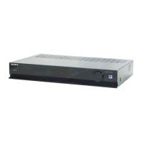
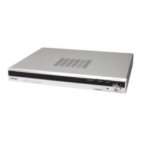
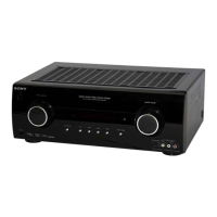
Rear panel
AM
ANTENNA
AUTO
CAL MIC
DMPORT
FRONT R
HDMI
EZW-T100
SPEAKERS
FRONT L SUR R SUR L CENTER
SUBWOOFER
DC5V 700mA MAX
BD IN OUTSAT INDVD IN
AUDIO IN
VIDEO 1
VIDEO 2
L
R
L
R
AUDIO IN
SA-CD
/
CD
COAX IN
SAT
OPT IN OPT INAUDIO IN
TV
DIGITAL
TV
" SPEAKERS section
Connects to the supplied speakers
and subwoofer.
# S-AIR (EZW-T100)
CAUTION
Please do not remove
the slot cover until
youwanttoinstall
the wireless
transmitter.
Connects to a
wireless transmitter
(not supplied).
$ DMPORT
DMPORT
jack
Connects to a
DIGITAL MEDIA
PORT adapter.
% AUTO CALIBRATION section
AUTO CAL
MIC jack
Connects to the
supplied optimizer
microphone for the
Auto Calibration
function.
& AUDIO INPUT section
AUDIO IN
jacks
Connects to a Super
Audio CD player,
CD player, etc.
With slot cover
slot
White (L)
Red (R)
' DIGITAL INPUT/OUTPUT section
OPT IN jacks Connects to a DVD
player, etc. The
COAX IN jack
provides a better
sound quality.
COAX IN
jack
HDMI IN/
OUT jacks
Connects to a DVD
player, satellite
tuner, or a Blu-ray
disc player. The
image is output to a
TV or a projector
while the sound can
be output from a TV
or/and speakers
connected to this
receiver .
( ANTENNA section
FM
ANTENNA
jack
Connects to the
supplied FM wire
antenna.
AM
ANTENNA
terminals
Connects to the
supplied AM loop
antenna.
(KS360S) (KS360)
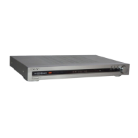
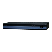
Rear panel
FRONT R
SPEAKERS
FRONT L SUR R SUR L CENTER
SUBWOOFER
AM
ANTENNA
AUTO
CAL MIC
DMPORT
HDMI
DC5V 700mA MAX
BD IN OUTSAT INDVD IN
AUDIO IN
VIDEO 1
VIDEO 2
L
R
L
R
AUDIO IN
SA-CD
/
CD
COAX IN
SAT
OPT IN OPT INAUDIO IN
TV
DIGITAL
TV
" SPEAKERS section
Connects to the supplied speakers
and subwoofer.
# DMPORT
DMPORT
jack
Connects to a
DIGITAL MEDIA
PORT adapter.
$ AUTO CALIBRATION section
AUTO CAL
MIC jack
Connects to the
supplied optimizer
microphone for the
Auto Calibration
function.
% AUDIO INPUT section
AUDIO IN
jacks
Connects to a Super
Audio CD player,
CD player, etc.
White (L)
Red (R)
& DIGITAL INPUT/OUTPUT section
OPT IN jacks Connects to a DVD
player, etc. The
COAX IN jack
provides a better
sound quality.
COAX IN
jack
HDMI IN/
OUT jacks
Connects to a DVD
player, satellite
tuner, or a Blu-ray
disc player. The
image is output to a
TV or a projector
while the sound can
be output from a TV
or/and speakers
connected to this
receiver.
' ANTENNA section
FM
ANTENNA
jack
Connects to the
supplied FM wire
antenna.
AM
ANTENNA
terminals
Connects to the
supplied AM loop
antenna.
w
w
w
.
x
i
a
o
y
u
1
6
3
.
c
o
m
Q
Q
3
7
6
3
1
5
1
5
0
9
9
2
8
9
4
2
9
8
T
E
L
1
3
9
4
2
2
9
6
5
1
3
9
9
2
8
9
4
2
9
8
0
5
1
5
1
3
6
7
3
Q
Q
TEL 13942296513 QQ 376315150 892498299
TEL 13942296513 QQ 376315150 892498299
http://www.xiaoyu163.com
http://www.xiaoyu163.com