EasyManua.ls Logo

Sony TC-366 - Page 31

Sony TC-366
53 pages
Print Icon
To Next Page IconTo Next Page
To Previous Page IconTo Previous Page
Loading...
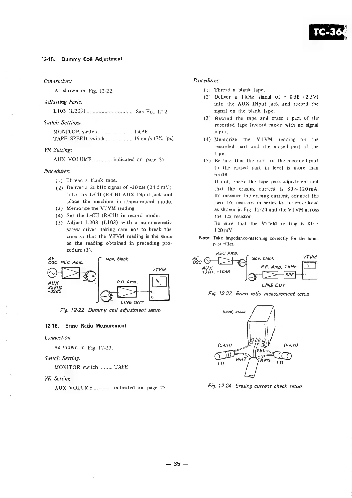
12-15.
Dummy
Coil
Adjustment
Connection:
As
shown
in
Fig.
12-22.
Adjusting
Parts:
T0306
203)
sete
tne
heehee:
See
Fig.
12-2
Switch
Settings:
MONITOR
switch
..............0..00
TAPE
TAPE
SPEED
switch
......0...0.0....
19
cm/s
(7%
ips)
VR
Setting:
AUX
VOLUME.............
indicated
on
page
25
Procedures:
(1)
Thread
a
blank
tape.
(2)
Deliver
a
20
kHz
signal
of
-30dB
(24.5
mV)
into
the
L-CH
(R-CH)
AUX
INput
jack
and
place
the
machine
in
stereo-record
mode.
(3)
Memorize
the
VTVM
reading.
(4)
Set
the
L-CH
(R-CH)
in
record
mode.
(5)
Adjust
L203
(L103)
with
a
non-magnetic
screw
driver,
taking
care
not
to
break
the
core
so
that
the
VITVM
reading
is
the
same
as
the
reading
obtained
in
preceding
pro-
cedure
(3).
AF
tape,
blank
OSC
REC
Amp.
VTVM
_
AUX
20
kHz
-30dB
LINE
OUT
Fig.
12-22
Dummy
coil
adjustment
setup
12-16.
Erase
Ratio
Measurement
Connection:
As
shown
in
Fig.
12-23.
Switch
Setting:
MONITOR
switch
.........
TAPE
VR
Setting:
AUX
VOLUME..............
indicated
on
page
25
Procedures:
(1)
Thread
a
blank
tape.
(2)
Deliver
a
1kHz
signal
of
+10dB
(2.5V)
into
the
AUX
INput
jack
and
record
the
signal
on
the
blank
tape.
(3)
Rewind
the
tape
and
erase
a
part
of
the
recorded
tape
(record
mode
with
no
signal
input).
(4)
Memorize
the
VIVM_
reading
on
the
recorded
part
and
the
erased
part
of
the
tape.
Be
sure
that
the
ratio
of
the
recorded
part
to
the
erased
part
in
level
is
more
than
65
dB.
If
not,
check
the
tape
pass
adjustment
and
that
the
erasing
current
is
80~120mA.
To
measure
the
erasing
current,
connect
the
two
1
resistors
in
series
to
the
erase
head
as
shown
in
Fig.
12-24
and
the
VTVM
across
the
19
resistor.
Be
sure
that
the
VTVM
reading
is
80~
120
mV.
Note:
Take
impedance-matching
correctly
for
the
band-
pass
filter.
(S
~
REC
Amp.
AF
tape,
blank
vivM
OSC
=o
AUX
1kHz,
+10dB
LINE
OUT
Fig.
12-23
Erase
ratio
measurement
setup
head,
erase
Fig.
12-24.
Erasing
current
check
setup