EasyManua.ls Logo

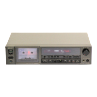
Sony TC-K555ES - FRONT PANEL CONTROLS - BASIC OPERATIONS; Power Switch and Eject Button; Tape Selection and Bias Control; Recording Level and Peak Meters

Sony TC-K555ES
67 pages
Print Icon
To Next Page IconTo Next Page
To Previous Page IconTo Previous Page
Loading...
TC-K555ES
1-2. FUNCTION OF CONTROLS
The
numbers
in
the
photo
are keyed
to
the
following
explanations.
TC-K5
COUNTER MEMORY
button
TAPE
select
buttons
and BIAS
control
e
Cassette
holder
TIMER
switch
REMOTE
control
connector
oPeak
program
meters
o DOLBY NR
switches
o MPX FILTER
switch
8
MONITOR
switch
and
indicator
REC LEVEL
(recording
level)
controls
HEADPHONES
level
control
Function
buttons
OPOWER
switch
Depress
this
switch
to
turn
on
the
power. The
lamp
in
the
cassette
holder,
the
display
of
the
peak
program
meter
and
the
tape
counter
will
light
up. The
indicator
lamp
of
the
pause
button
will
blink
for
about
4 seconds,
indicating
that
the
function
buttons
are in-
operative
during
this
period.
Press
this
switch
again
to
turn
the
power
off.
~
(eject)
button
Press
this
button
to
open
the
cassette
holder.
eTAPE
select
buttons
and BIAS
control
Depress one
of
the
TAPE
select
buttons
according
to
the
type
of
tape
to
be used. When
the
appropriate
button
is depressed,
the
op-
timum
equalization
and
bias
current
settings
are
obtained
for
recording, and
the
optimum
equalization
setting
is
obtained
for
playback. When
recording
using
a TYPE I (NORM), TYPE
II
(Cr0
2
)
or
TYPE III (Fe-Cr) tape,
adjust
the
BIAS
control.
See
"Recommended
settings
for
the
TAPE
select
buttons
and
the
BIAS
control':
on
page
11.
.Peak
program meters
With
the
MONITOR
switch
set
to
SOURCE,
the
meters
show
the
peak
input
level
of
each channel, and
to
TAPE,
the
meters
show
recorded levels. They
follow
the
transient
peaks
of
high-level
inputs
that
are
too
brief
to
be
followed
by
conventional
VU
meters
so
that
the
optimum
recording
level can be
accurately
set. The
highest
in-
put
of
each
channel
is held
about
4
seconds
on
the
scale,
except
when a
higher
peak
occurs
before
4
seconds
have passed, in
which
case
that
peak is
immediately
indicated.
-9-
GOOLBY
NR
switches
The
left
switch
turns
the
Dolby
NR
* (Noise Reduction)
system
on
and
off
and
the
right
switch
selects
either
the
B-type
or
C-type
Dolby NR system.
To record
with
the
Dolby NR process, depress
the
ON/OFF
switch
to
the
ON
position
and
choose
B-TYPE
(n
) or C-TYPE
(.D.
).
To record
without
the
Dolby NR process, press
the
ON/OFF
switch
again
to
release.
When
playing
back, set
these
switches
to
the
same
position
used
in recording.
*
"Dolby"
and
the
double-D
symbol
are
trade
marks
of
the
Dolby
Laboratories
Licensing
Corporation.
Noise
reduction
system
manufactured
under
license
from
Dolby
Laboratories
Licensing
Corporation.
OMPX
FILTER
switch
Normally
set
this
switch
to
OFF.
When recording FM stereo
broadcasts
with
the
Dolby NR system,
set it
to
ON
if
the
19
kHz
pilot
signal
and
the
38
kHz
subcarrier
have
not
been
adequately
suppressed by
the
FM
tuner
or
receiver.
If
the
tuner
or
the
receiver
suppresses
such
signals
adequately
(most
high-quality
tuners
and receivers will), you
do
not
have
to
set
this
switch
to
ON.
MONITOR
switch
and
indicator
When
adjusting
the
recording level, set
this
switch
to
the
released
position
(SOURCE
n)
to
allow
monitoring
of
the
sound
to
be
recorded. During
playback,
depress
this
switch
(TAPE
0.)
to
allow
monitoring
of
the
recorded sound.
According
to
the
MONITOR
switch
setting,
"SOURCE"
or
"TAPE"
will
appear in
the
indicator
window.
During recording, use
this
switch
to
monitor
either
the
source
or
the
recorded sound.

Related product manuals