18
KV-28WF3/32WF3
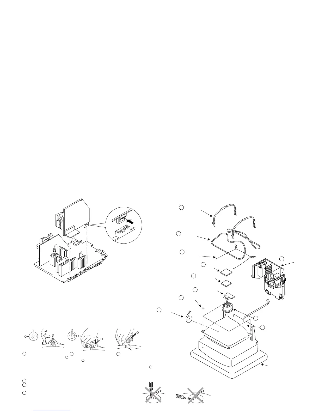
2-5. A BOARD REMOVAL
Release the clip indicated.
2-6. PICTURE TUBE REMOVAL
Cushion
10 Four PT screws (M)
3 C board
1 Anode cap
8 Degaussing coils
9 Spring Extension
7 Two DGC holders
6 Deflection yolk
4 VM Board
5 Neck assy
11 Picture tube
2 Chassis assy
Anode button
a
* REMOVING PROCEDURES.
Turn up one side of the rubber cap in
the direction indicated by the arrow a
1
2 Using a thumb pull up the rubber cap
firmly in the direction indicated by the
arrow b
3 When one side of the rubber cap is
separated from the anode button, the
anode-cap can be removed by turning
up the rubber cap and pulling it up in
the direction of the arrow c
b
b
c
Note : Short circuit the anode of the picture tube and the anode cap to the metal chassis, CRT
shield or carbon paint on the CRT, after removing the anode.
• REMOVAL OF ANODE-CAP
• HOW TO HANDLE THE ANODE-CAP
1 To prevent damaging the surface of the anode-cap do not use sharp materials.
2 Do not apply too great a pressure on the rubber, as this may cause damage to the
anode connector.
3 A metal fitting called a shatter hook terminal is fitted inside the rubber cap.
Do not turn the rubber foot over excessively this may cause damage if the shatter
hook sticks out.