EasyManua.ls Logo

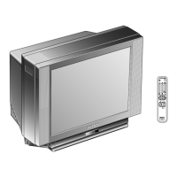
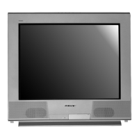
Sony Trinitron KV-29FX65E User Manual

Sony Trinitron KV-29FX65E
84 pages
To Next Page IconTo Next Page
Page #1 background imageLoading...
Page #1 background image
1
SERVICE MANUAL
AE-5
CHASSIS
MODEL
COMMANDER DEST CHASSIS NO.
KV-29FX65B
RM-887 FRENCH SCC-Q13H-A
KV-29FX65E
RM-887 ESP SCC-Q14H-A
MODEL
COMMANDER DEST CHASSIS NO.
KV-29FX65K
RM-887 OIRT SCC-Q16L-A
p
- +
4
MONO
4
L/G/S/I
R/D/D/D
s
4
Question and Answer IconNeed help?

Do you have a question about the Sony Trinitron KV-29FX65E and is the answer not in the manual?

Sony Trinitron KV-29FX65E Specifications

General IconGeneral
BrandSony
ModelTrinitron KV-29FX65E
CategoryTV
LanguageEnglish

Summary

AE-5 SELF DIAGNOSTIC SOFTWARE

Error Detection Monitor

Mechanism for identifying TV errors.

Error Monitor Menu

Procedure to access stored error logs.

Error Reader Display

Displays specific error codes and messages.

GENERAL

Tuning your TV

Process for channel tuning.

Finding your Video Channel

Steps to locate video input channels.

NexTView Operation

Explains the electronic program guide feature.

Operation using the Sony navigation

Describes remote control usage for NexTView.

Teletext Operation

Explains Teletext functions and usage.

Using the TV menu system

Navigating and adjusting TV settings via menus.

Troubleshooting

Solutions for common TV problems.

DISASSEMBLY

Rear Cover Removal

Step-by-step guide to remove the rear cover.

Chassis Removal

Procedure for removing the main chassis assembly.

Picture Tube Removal

Detailed steps for removing the CRT.

SET-UP ADJUSTMENTS

Beam Landing

Adjustment for electron beam alignment.

Convergence

Alignment of red, green, and blue electron beams.

Focus, Screen [G2] Adjustment

Adjusting picture focus and screen brightness.

White Balance Adjustment

Calibrating color reproduction.

CIRCUIT ADJUSTMENTS

Electrical Adjustments

Performing service adjustments via the service menu.

Test Mode 2

Accessing and using diagnostic test modes.

DIAGRAMS

BLOCK DIAGRAMS (1)

High-level system overview.

Circuit Board Location

Physical placement of PCBs.

EXPLODED VIEWS

CHASSIS

Exploded view of the chassis assembly.

PICTURE TUBE

Exploded view of the picture tube components.

ELECTRICAL PARTS LIST

Related product manuals