— 17 —
KV-32FV1/34FVL1/36FV1
ELECTRICAL ADJUSTMENT BY REMOTE COMMANDER
NOTE : Test Equipment Required:
1. Pattern Generator
2. Frequency Counter
3. Digital Multimeter
4. Audio OSC
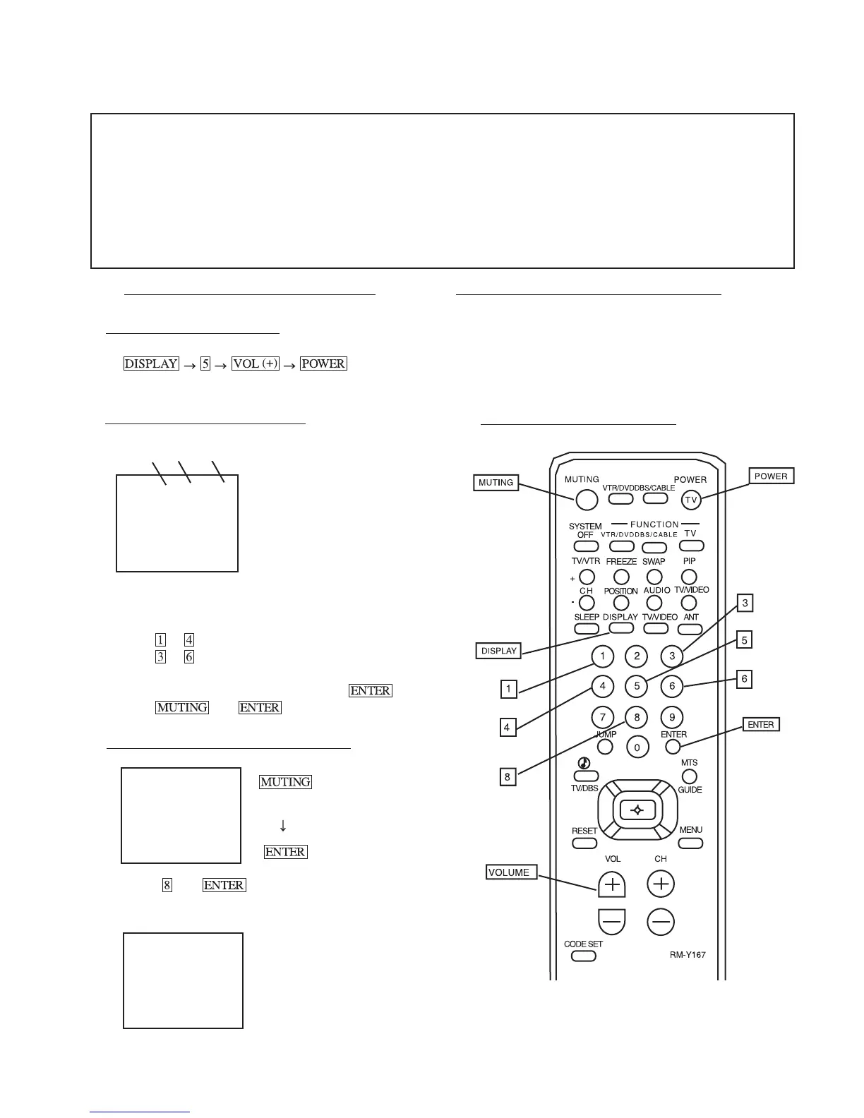
(1) Setting the Service Adjustment Mode
SERVICE MODE PROCEDURE
1. Standby mode. (Power off)
2.
on the Remote
Commander. (Press each button within a second.)
SERVICE ADJUSTMENT MODE IN
3. The CRT displays the item being adjusted.
4. Press
2
or
5
on the Remote Commander to select the device item.
5. Press
or on the Remote Commander to select the item.
6. Press
or on the Remote Commander to change the
data.
7. To recover the latest values, press "0" then
.
8. Press
then to write into memory.
SERVICE ADJUSTMENT MODE MEMORY
Green
9. Press
then on the Remote Commander to reset.
SECTION 5
CIRCUIT ADJUSTMENTS
(Write into memory)
(Write into memory)
(Service Mode)
(Item up)
(Item down)
(Initialize)
(Data up)
(Device Item down)
(Data down)
(Service mode)
SERVICE VP VPOS 30
1000 0
Use Remote Commander (RM-Y167) to perform the following circuit adjustments:
Red
SERVICE VP VPOS 30
1000 0
RM-Y167
Carry out step 8 when adjusting
IDs 0 to 4 and when replacing
and adjusting IC102.
SERVICE WRITE
10. Turn set off and on to exit.
(3) Adjust Buttons and Indicator
(2) Memory Write Confirmation Method
1. After adjustment, pull out the plug from the AC outlet,
then replace the plug in the AC outlet again.
2. Turn the power switch ON and set to Service Mode.
3. Call the adjusted items again to confirm they were adjusted.
Disp.
(Item)
Item
data
Device Item
Register Item
Data Item
1000 0000