SONY CORPORATION
Sony Technology Center
Product Quality Division
Service Promotion Department
3-4: SCREEN (G2) (page 20)
English
99JJ74347-1
Printed in U.S.A.
© 1999.10
9-965-868-94
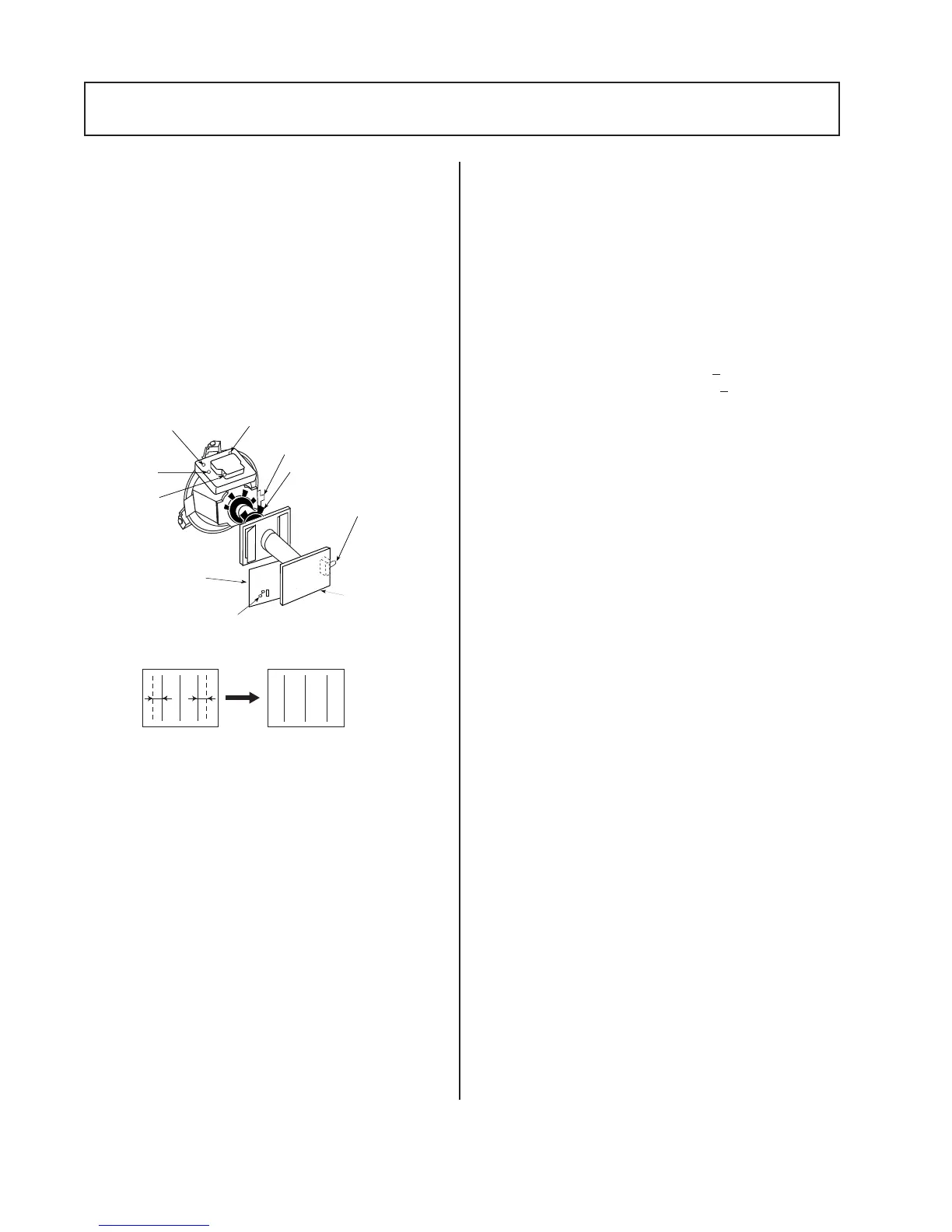
TLH Plate
YCH
RV1750
V.STAT
XCV
TLV
(TLV)
C Board
Y Magnet
WA Board
RV 941
H-TRAP
1. Input dot pattern from the pattern generator.
2. Set the user controls to normal.
3. Adjust RCUT, GCUT, BCUT, and SBRT in service
mode with an oscilloscope so that voltages on the red,
green, and blue cathodes are 170
+2 V DC or with a
voltmeter so that cathodes are 176
+2 V DC.
4. Observe the screen and adjust SCREEN (G2) VR to
obtain the fairly visible background of dot signal.
5. Push the TEST +JUMP (+Channel) to cut off the
signal, then the screen is bright or dark. Brightness of
raster must be increased when adjusting.
6. Adjust screen VR until the screen is just cut off, or
scarcely lights up. A signal cannot be seen when the
brightness of the raster is high.
7. Push the JUMP again to release the cut off.
• Input a crosshatch pattern.
• Adjust PICTURE QUALITY to standard, PICTURE
and BRIGHTNESS to 50% and OTHER to standard.
• Adjust the Horizontal Convergence of red and blue
dots by tilting the TLH plate on the deflection yoke.
1. Adjust XCV core to balance X axis.
2. Adjust YCH VR to balance Y axis.
3. Adjust vertical red and blue convergence with V.TILT (TLV
VR.)
Perform adjustments while tracking items 1 and 2.
4. Adjust Y MAGNET to correct V.BOW Geometry Distor-
tion.
5. Adjust H-TRAP (VR-941) to correct H.TRAPEZOID
Geometry Distortion.
After adjusting items 4 and 5, confirm overall geometry again.
B R R B
(R)(B) (B)(R)
TLH+
TLH-
☛
☛
☛
☛
SECTION 3
SET-UP ADJUSTMENTS
: Corrected item
3-2: CONVERGENCE
(4) TLH Plate Adjustment (page 19)
KV-32FS10/32FV15/32XBR250/34FV10/34FV15/34FV15C/34FX250C/34FV15K/
34FV15T/36FS10/36FV15/36XBR250/38FX250/38FX250C/38FX250T/38FV15K



 To Next Page