EasyManua.ls Logo

Sony TRINITRON KV-36FS10 User Manual

Sony TRINITRON KV-36FS10
104 pages
To Next Page IconTo Next Page
Page #1 background imageLoading...
Page #1 background image
1
KV-32FS10/32FV15/32XBR250/34FV10/34FV15/34FV15C/34FX250C/34FV15K
34FV15T/36FS10/36FV15/36XBR250/38FX250/38FX250C/38FX250T/38FV15K
TRINITRON
®
COLOR TV
MODEL DEST. COMMANDER CHASSIS NO.
KV-32FS10
U.S. RM-Y168 SCC-S32B-A
KV-32FS10
CND RM-Y168 SCC-S33B-A
KV-36FS10
U.S. RM-Y168 SCC-S32C-A
KV-36FS10
CND RM-Y168 SCC-S33C-A
KV-32FV15
U.S. RM-Y171 SCC-S32D-A
KV-32FV15
CND RM-Y171 SCC-S33D-A
KV-34FV10
E RM-Y168 SCC-S34E-A
KV-34FV15
E RM-Y171 SCC-S34F-A
KV-34FV15C
E RM-Y171 SCC-S34G-A
KV-34FV15K
KOREA RM-Y149A SCC-S31B-A
KV-34FV15T
TAIWAN RM-Y171 SCC-S36A-A
KV-36FV15
U.S. RM-Y171 SCC-S32G-A
KV-36FV15
CND RM-Y171 SCC-S33G-A
KV-38FV15K
KOREA RM-Y149A SCC-S31C-A
KV-34FX250C
E RM-Y170 SCC-S34H-A
KV-38FX250
E RM-Y170 SCC-S34M-A
KV-38FX250C
E RM-Y170 SCC-S34J-A
KV-38FX250T
TAIWAN RM-Y170 SCC-S36B-A
KV-32XBR250
U.S. RM-Y170 SCC-S32E-A
KV-32XBR250
CND RM-Y170 SCC-S33E-A
KV-36XBR250
U.S. RM-Y170 SCC-S32F-A
KV-36XBR250
CND RM-Y170 SCC-S33F-A
KV-36XBR250
SERVICE MANUAL
CHASSIS
AA-2W
RM-Y170

Table of Contents

Question and Answer IconNeed help?

Do you have a question about the Sony TRINITRON KV-36FS10 and is the answer not in the manual?
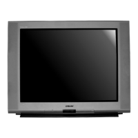
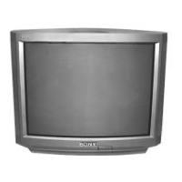
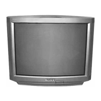
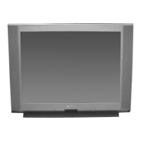
Sony TRINITRON KV-36FS10 Specifications

General IconGeneral
Screen Size36 inches
Display TypeCRT
Resolution480i
Aspect Ratio4:3
Comb Filter3D Digital Comb Filter
Speakers2
InputsComposite, S-Video, Component

Summary

Specifications

Optional Accessories

Lists optional items like connecting cables and TV stands for enhanced functionality.

Section 1 General

Connecting and Installing the TV

Instructions for connecting external equipment like cable boxes and VCRs to the TV.

Using Your New TV

Guidance on basic setup, remote control usage, and front panel controls for new users.

Using Your Menus

Explains navigation and adjustment of on-screen menus for picture, audio, timer, and setup.

Operating Video Equipment

Instructions for operating VCRs, Laserdisc players, DVD players, and programming the remote.

Troubleshooting

Provides solutions for common TV operational problems and their potential causes.

Safety Check-Out

Leakage Test Procedures

Detailed steps to test AC leakage from exposed metal parts for user safety.

Earth Ground Finding

Explains how to identify and verify a proper earth ground connection for safety testing.

Section 2 Disassembly Procedures

Rear Cover and Chassis Removal

Step-by-step instructions for removing the TV's rear cover and chassis assembly.

Picture Tube Removal and Handling

Detailed steps for safely removing the picture tube and handling the anode cap.

Section 3 Set-Up Adjustments

Beam Landing

Procedure for adjusting beam landing for proper picture alignment and purity.

Convergence Adjustments

Detailed instructions for adjusting picture convergence for accurate color alignment.

Focus, Screen (G2), and White Balance

Procedures for adjusting focus, screen grid voltage, and white balance for optimal picture.

Section 4 Safety Related Adjustments

Component Confirmation and Voltage Adjustment

Procedures to confirm and adjust critical component values and voltages for safety.

Section 5 Circuit Adjustments

Service Adjustment Mode Procedures

Step-by-step guide to entering the TV's service adjustment mode for internal settings.

Service Data Tables

Detailed service data including register names, ranges, and initial/average values.

Section 6 Diagrams and Schematics

Block Diagrams

Illustrates the overall functional blocks of the TV's internal circuitry.

Circuit Board Locations

Identifies the physical location of the various circuit boards within the TV chassis.

Printed Wiring Boards and Schematics

Provides detailed schematic diagrams and printed wiring board layouts for technical analysis.

Section 7 Exploded View

Chassis Exploded View

Exploded view of the TV chassis, listing part numbers for main assemblies.

Picture Tube Exploded View

Exploded view of the picture tube and its associated components.

Section 8 Electrical Parts List

Board Specific Parts Lists

Detailed lists of electrical parts for each major board (A, C, G, GA, HA, HB, HX, T, UX, UY, WA).

Accessories and Remote Commander

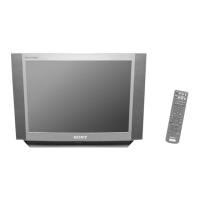
Lists included accessories, packing materials, and details about the remote commander.

Correction-1: A Board Schematic

Correction-2: IC002 Part Number

Correction-3: G Board Schematic

Correction-4: Set-up Adjustments

Supplement-1: HZ Board Updates

HZ Board Schematic Diagram

Schematic diagram for the HZ board, showing its electrical connections and modifications.

HZ Board Electrical Parts

Lists electrical components for the HZ board, including connectors and switches.

Related product manuals