EasyManua.ls Logo

Sony Trinitron KV-32TW77 User Manual

Sony Trinitron KV-32TW77
79 pages
To Next Page IconTo Next Page
Page #1 background imageLoading...
Page #1 background image
Television
system
Channel
coverage
Picture
tube
Antenna
~—
KV-27TW77/271W78
__KV-32TW77/32TW78
SERVICE
MANUAL
CUT
ASSO
O10)
i
G¥Oeso
ToT
Ootan
ocdyetsic>asc0
|
H
,
,
1
i
Fy
;
|
X
KV-27TW77/27TW78
|
KV-27TS29/27TS32/27TS36
KV-32TW77/32TW78
|
KV-32TS36/32TS46
KV-2970RS
/2970M/2975M
SPECIFICATIONS
American
TV
standards
Input
VHF:
2-13
UHF:
14-69
Cable
TV:
1-125
Hi-Black
Trinitron®
tube
27-inch
picture
measured
diagonally
29-inch
picture
tube
measured
diagonally
(KV-27TW77/27TW78)
32-inch
picture
measured
diagonally
34-inch
picture
tube
measured
~
diagonally
(KV-32TW77/32TW78)
Output
75-ohm
external
antenna
terminal
for
;
VHF/UHF
.
2
RM-Y118
US
Model
KV-27TW/77
Chassis
No.
SCC-F84F-A
KV-27TW78
Chassis
No.
SCC-F84G-A.
KV-32TW/77
Chassis
No.
SCC-F84J-A
KV-32TW/78
Chassis
No.
SCC-F84K-A
AA-
1
CHASSIS
MODELS
OF
THE
SAME
SERIES
.
VIDEO
and
S
VIDEO
S
VIDEO
IN
(S
terminal)
Y:
1
Vp-p,
75-ohms
unbalanced,
sync
negative
C:.0.286
Vp-p
(Burst
signal),
75-ohms
Video
(phono
jacks):
1
Vp-p,
75-ohms
unbalanced,
sync
negative
Audio
(phono
jacks):
500
mVrms
(100%
modulation)
Impedance:
47
kilohms
AUDIO
OUT
(phono
jacks)
.
More
than
408
mVrms
at
the
maximum
volume
setting
(variable)
More
than
408
mVrms
(fix)
impedances:
5
kilohms
Continued
on
next
page
TRINITRON©
COLOR
TV
SONY.
Question and Answer IconNeed help?

Do you have a question about the Sony Trinitron KV-32TW77 and is the answer not in the manual?

Sony Trinitron KV-32TW77 Specifications

General IconGeneral
BrandSony
ModelTrinitron KV-32TW77
CategoryTV
LanguageEnglish

Summary

Service Manual

General Specifications

Details key technical specifications for television system, channel coverage, picture tube, and inputs/outputs.

Safety and Accessories

Critical Safety Warnings

Highlights crucial safety precautions, including anode handling and electrical shock hazards.

Safety Check-Out Procedures

AC Leakage Testing

Steps for performing an AC leakage test on exposed metal parts.

Establishing Earth Ground Connection

Methods for ensuring a proper earth ground connection for safety tests.

General Information (Continued)

Automatic Channel Presetting

Procedure for scanning and storing all available TV channels automatically.

Picture-in-Picture (PIP) Operation

Comprehensive guide on using the PIP feature to watch two video sources simultaneously.

ON/OFF Timer Programming

How to set the TV to turn on or off automatically at a scheduled time.

Channel Blocking Configuration

Procedure for blocking specific channels to prevent unauthorized viewing.

Disassembly Procedures

Disassembly Procedures (Continued)

Picture Tube Removal (KV-27TW77/27TW78)

Detailed instructions for safely removing the picture tube, including anode cap procedures.

Picture Tube Removal (KV-32TW77/32TW78)

Detailed instructions for safely removing the picture tube, including anode cap procedures.

Chip Component Soldering and Repair

Guidelines for soldering and repairing circuit boards with surface-mount chip components.

Set-Up Adjustments

Beam Landing Adjustment Procedure

Steps for aligning the electron beam to ensure correct picture geometry and purity.

Set-Up Adjustments (Continued)

Static Convergence Adjustment

Adjusting horizontal and vertical convergence for proper color alignment at the screen center.

Dynamic Convergence Adjustment Techniques

Procedures for optimizing dynamic convergence using deflection yoke and magnets.

Focus Adjustment Procedure

How to adjust the focus control on the flyback transformer for a clear picture.

G2 (Screen) and White Balance Calibration

Adjusting screen bias and white balance for accurate color reproduction.

Safety Related Adjustments

R511 Hold-Down Confirmation and Readjustment

Procedure to verify and adjust safety circuit R511 after component replacement.

R524 Hold-Down Confirmation and Readjustment

Procedure to verify and adjust safety circuit R524 after component replacement.

Safety Related Adjustments (Continued)

B+ Voltage Confirmation Procedure

Steps to confirm the B+ voltage, a critical safety parameter, after repairs.

Circuit Adjustments

Electrical Adjustment via Remote Commander

Using the remote commander to access and perform internal electrical adjustments.

Circuit Adjustments (Continued)

M Board Frequency Adjustments (HFRE/VFRE)

Specific procedures for adjusting the H.Frequency (HFRE) and V.Frequency (VFRE) on the M board.

Horizontal and Vertical Geometry Adjustments

Instructions for adjusting H/V Center, Size, Linearity, and Correction parameters.

Chroma Trap and P Board Adjustments

Procedures for adjusting the Chroma Trap (CROM) and P Board Position (PHPO).

Diagrams

Diagrams (Continued)

Semiconductor Identification

Visual identification and part numbers for various semiconductor devices.

Exploded Views

Chassis Assembly Breakdown

An exploded view diagram showing the parts and assembly of the TV chassis.

Exploded Views (Continued)

Outer Cover Assembly Breakdown

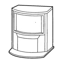
An exploded view diagram illustrating the disassembly of the TV's outer covers and panels.

Picture Tube Assembly Breakdown

An exploded view detailing the parts and assembly related to the TV's picture tube.

Electrical Parts List

Electrical Parts List (Continued)

Related product manuals