4
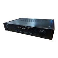
Parts Identification
Parts
Identification
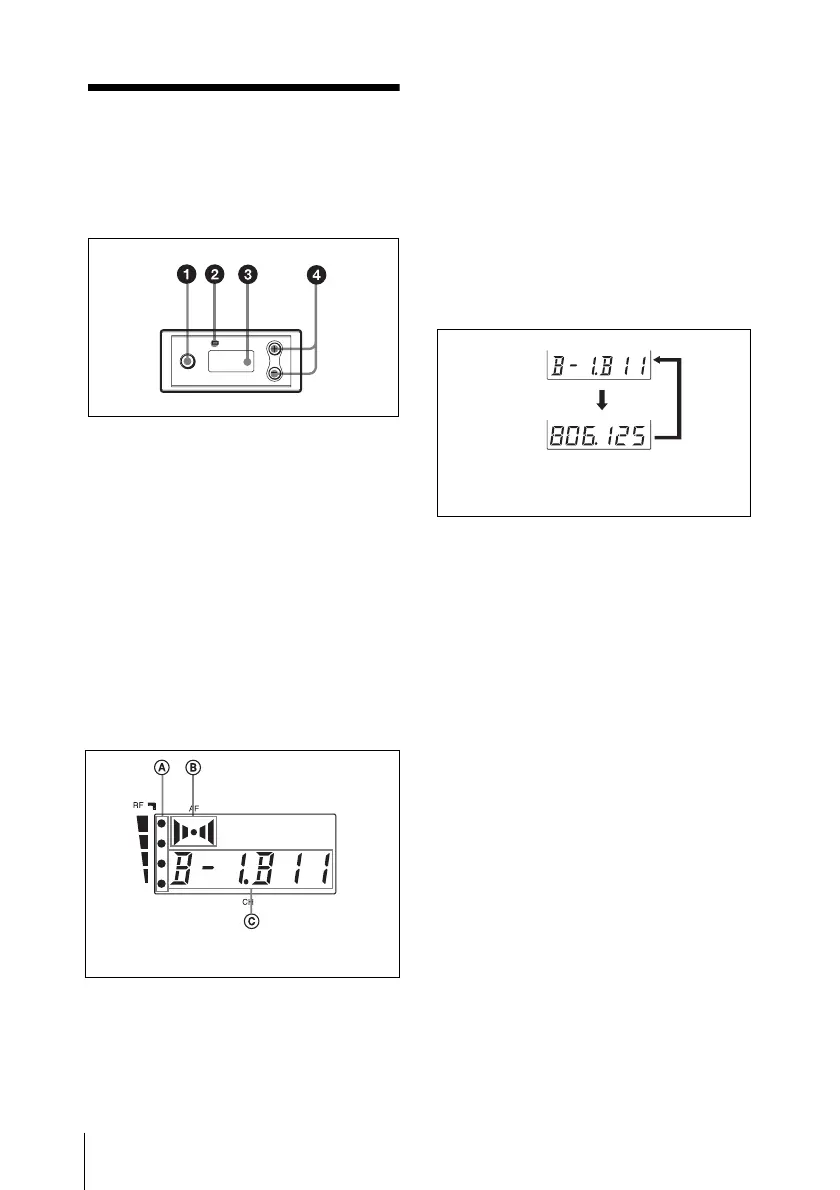
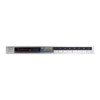
a SET button
Press to change and enter display
parameters.
For details, see “Tuner Settings” on page 8.
b RF (radio frequency) indicator
The color indicates the strength of the RF
input signal.
On (green): RF input is 25 dBµ
1)
or more.
Off: RF input is less than 25 dBµ
1)
.
1) 0 dBµ = 1 µVEMF
c Display section
A RF (radio frequency) indications
The number of dots indicates the RF input
level.
B AF (audio frequency) indication
Appears whenever the output audio signal
is stronger than the reference level.
C GP (group)/CH (channel) indication
Shows the reception channel group and
channel number. Each time you press the
SET button, the channel indication changes
as follows.
For details, see“Tuner Settings” on page 8.
d + (+ selection) / – (– selection/reset)
buttons
Press these buttons to set the reception
channel and frequency.
The channel indication (C) for
U30 model is shown.
Reception
channel group
and number
Reception
frequency
The channel/frequency indications for
U30 model are shown.
Press
the
SET
button.