– 31 –
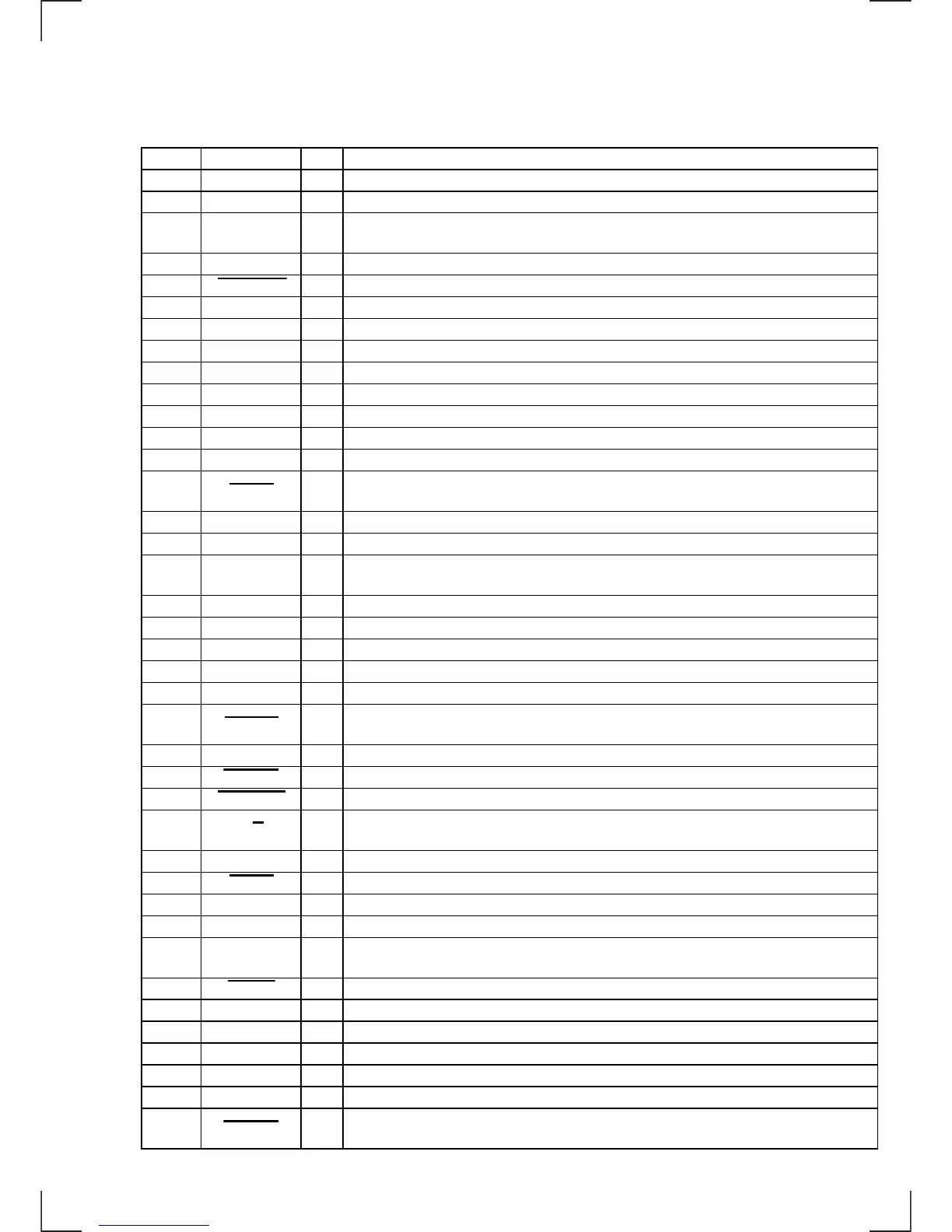
5-7. IC PIN FUNCTION DESCRIPTION
• MAIN BOARD IC1 MN1884820SF (SYSTEM CONTROLLER)
Pin No. Pin Name I/O Function
1 TUNMUT O FM audio signal muting control output terminal “H”: muting on
2 AMPON O Standby control signal output to the power amplifier (IC500) “L”: standby
3 ILLON O
Power supply on/off control signal output terminal at the illumination and liquid crystal display
driver (IC900) “H”: power on
4 PW ON O Main system power supply on/off control signal output terminal “H”: power on
5 AMPMUTE O Muting control signal output to the power amplifier (IC500) “L”: muting on
6 NIL I Not used (fixed at “L”)
7 VDD1 — Power supply terminal (+5V)
8 X IN I Main system clock input terminal (8 MHz)
9 X OUT O Main system clock output terminal (8 MHz)
10 GND — Ground terminal
11 XT IN I Sub system clock input terminal (32.768 kHz)
12 XT OUT O Sub system clock output terminal (32.768 kHz)
13 EX2 I Connected to ground
14 RESET I
System reset signal input from the reset signal generator (IC50) and reset switch (S2)
“L” is input for several 100 msec after power on, then it changes to “H”
15 RDSCKI I Serial data transfer clock signal input from the RDS decoder (IC150)
16 BU IN I Battery detect signal input terminal “H”: battery on
17 KEYACK I
Input of acknowledge signal for the key entry Acknowledge signal is input to accept function
and eject keys in the power off status On at input of “H”
18 VOLSO O Serial data output to the electrical volume (IC450)
19 VOLCKO O Serial data transfer clock signal output to the electrical volume (IC450)
20 VOLCE O Chip enable signal output to the electrical volume (IC450)
21 TAPE MUTE O Tape muting on/off control signal output terminal “H”: tape muting on Not used (open)
22 to 24 NCO O Not used (open)
25 AMS ON O
Tape auto music sensor control signal output terminal
“L” is output to lower the gain for audio level at FF/REW Not used (open)
26 ATA ON I Not used (fixed at “H”)
27 TAPE IN I Tape in detection switch (S903) input terminal “L”: tape in
28 FF-REW IN I FF/REW detection switch (S902) input terminal “L”: FF/REW mode
29 N/R I
Tape direction switch (S901) input terminal
“L: reverse direction, “H”: forward direction
30 RDSSI I Serial data input from the RDS decoder (IC150)
31 AD ON O Power supply on/off control signal output for the A/D converter “L”: power on
32, 33 NCO O Not used (open)
34 CM ON O Capstan/reel motor (M901) drive signal output terminal “H”: motor on
35 TAPE ON O
Tape system power supply on/off control signal output terminal “H”: tape on
Not used (open)
36 ACC IN I Accessory detect signal input terminal “L”: accessory on
37 PLLSI I PLL serial data input from the FM/AM PLL (IC121)
38 BEEP O Beep sound signal output terminal
39 PLLSO O PLL serial data output to the FM/AM PLL (IC121)
40 PLLCLK O PLL serial data transfer clock signal output to the FM/AM PLL (IC121)
41 PLLCE O PLL serial chip enable output to the FM/AM PLL (IC121)
42 LCD INH O
Blank indicate control signal output to the liquid crystal display driver (IC900)
“L”: no display
 Loading...