2
TABLE OF CONTENTS
1. SERVICE NOTE
............................................................. 2
2. GENERAL ........................................................................ 3
3. DISASSEMBLY .............................................................. 13
4. ASSEMBLY OF MECHANISM DECK................ 14
5. MECHANICAL ADJUSTMENTS ............................ 17
6. ELECTRICAL ADJUSTMENTS
6-1. Test Mode ........................................................................ 17
• Tape Deck Section ........................................................ 17
• Tuner Section................................................................ 17
7. DIAGRAMS
7-1. Block Diagrams
• TUNER/TAPE/MAIN Section ..................................... 18
• DISPLAY/KEY CONTROL/BUS CONTROL/
POWER SUPPLY Section ........................................... 19
7-2. Printed Wiring Board – MAIN Board – ......................... 21
7-3. Schematic Diagram – MAIN Board (1/2) – ................... 22
7-4. Schematic Diagram – MAIN Board (2/2) – ................... 23
7-5. Printed Wiring Boards – KEY/SUB Boards – .............. 24
7-6. Schematic Diagrams – KEY/SUB Boards – .................. 25
7-7. IC Block Diagrams ......................................................... 26
7-8. IC Pin Function ............................................................... 27
8. EXPLODED VIEWS ................................................ 32
9. ELECTRICAL PARTS LIST ............................... 35
Flexible Circuit Board Repairing
• Keep the temperature of the soldering iron around 270 ˚C dur-
ing repairing.
• Do not touch the soldering iron on the same conductor of the
circuit board (within 3 times).
• Be careful not to apply force on the conductor when soldering
or unsoldering.
Notes on chip component replacement
• Never reuse a disconnected chip component.
• Notice that the minus side of a tantalum capacitor may be dam-
aged by heat.
SECTION 1
SERVICE NOTE
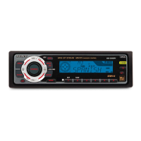
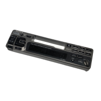
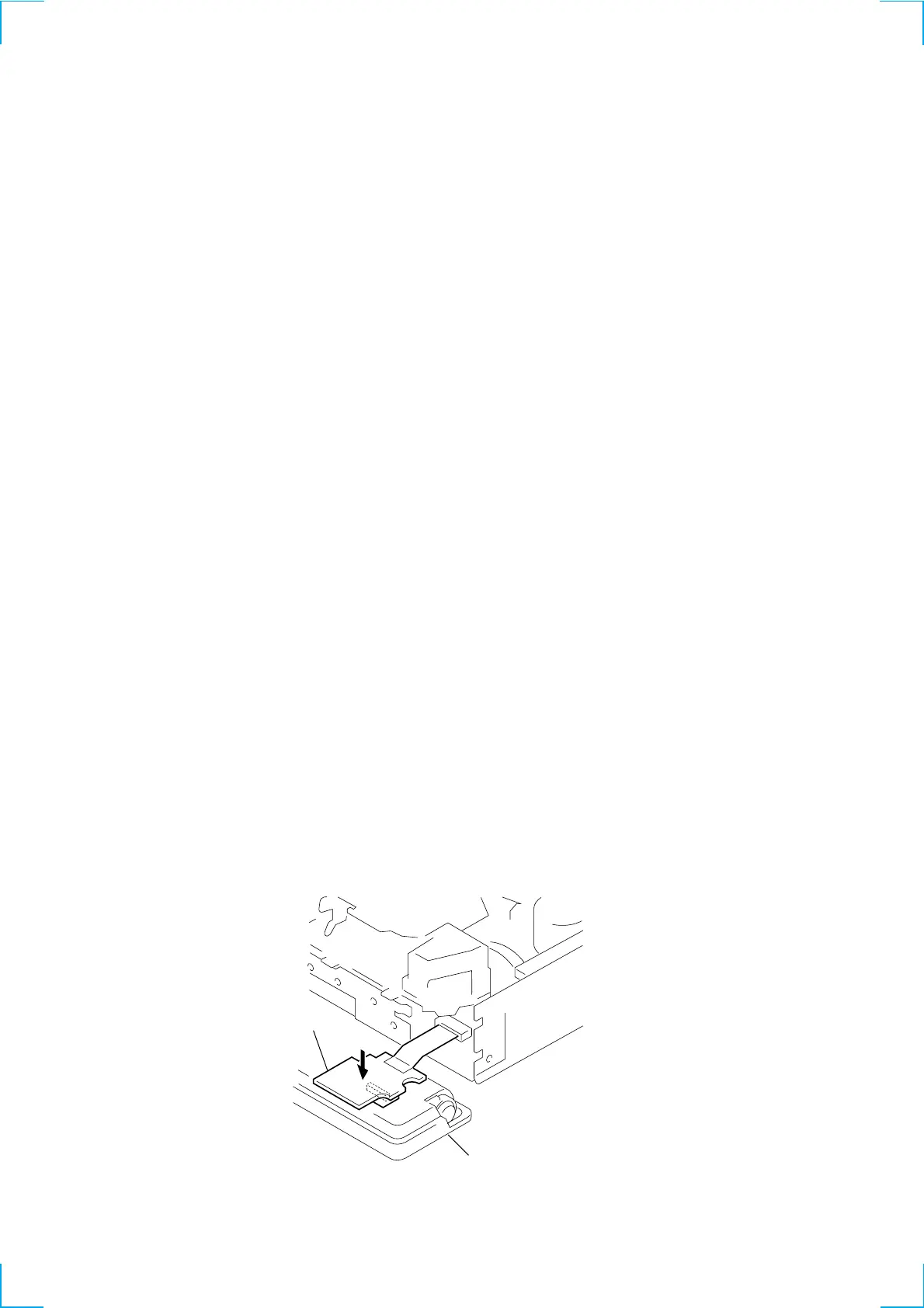
SUB board
Front panel assembly
Please press on the sub board from above when checking it.
This assures that the connector does not lose contact.
 Loading...