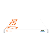
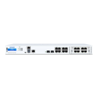
3. Rear Connections & Cabling
Slide rail/mounted equipment is not to
be used as a shelf or a work space.
Step 2 - Configure the Sophos Appliance
Do not interrupt the installer once it begins. Doing so can damage the system to a
point that it may require return to the factory to be re-imaged.
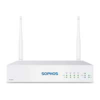
Step 1 - Configuring Ports
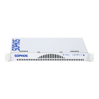
Remove the front bezel if it is installed on the appliance.
1. Press in on the left side of the bezel to release the tabs from the ears.
2. Swing the bezel forward to remove it.
3. Press the I/O Power Button located on the far right on the front panel.
4. Once the appliance has been powered on, replace the bezel.
4. Front Panel Operation
5. Software/Network Setup
22 1
Online documentation at http://swa.sophos.com/docs/swa
To ensure the functionality of the Sophos Web Appliance, configure your network to allow access on the ports listed below. Some ports are required only for specific situation, such as when you
enable FTP backups or central management.
These services are typically used for connections between your Web Appliance(s) and locations outside of your organization’s network.
Port Function Service Protocol Connection
22 Remote assistance SSH TCP Outbound from appliance to sophos.com
22 Central configuration, status and reporting SSH TCP Outbound from Web Appliance to Management Appliance (if not collocated)
25 Remote assistance notification SMTP TCP Outbound from appliance to sophos.com
80 Outbound network web traffic HTTP TCP Outbound from appliance to internet
123 Network time synchronization NTP UDP Outbound from appliance to internet
443 Outbound network web traffic HTTPS TCP Outbound from appliance to internet
To launch the Sophos Appliance configuration wizard:
• On your laptop or PC, set the subnet mask to 255.255.255.0 and the IP address to 172.24.24.1
• Using a supported browser, connect to https://172.24.24.173
You may need to add this address to your browser's Trusted Sites.
When prompted, accept the certificate. Once you have completed the setup wizard, you may disconnect your laptop or PC.
• Disconnect your laptop from the “Config” port. Do not connect the “Config” port to your LAN.
1
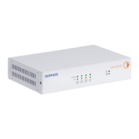
Multi-function LED
Blue LED
Unit identification
indicator
Red LED
Fan fail overheat
indicator
Reset
I/0 PowerPower
HDD
NIC1
NIC2
2
External Connections
These services are typically used for connections within your organization’s network and your Web Appliance(s), or between appliances
themselves, if you have multiple appliances.
Port Function Service Protocol Connection
21 Backups using passive FTP FTP TCP Outbound from appliance to FTP server
22 Central configuration, status and reporting SSH TCP Outbound from Web Appliance to Management Appliance (if collocated)
53 DNS queries DNS UDP Outbound from Appliance to LAN
80 administrative web interface HTTP TCP Inbound from LAN to appliance
88 Kerberos authentication KERBEROS TCP/UDP Inbound/outbound between appliance and AD server
139 MS NetBIOS session NETBIOS-SSN TCP/UDP Inbound/outbound between appliance and AD server
389 Directory services synchronization LDAP TCP/UDP Inbound/outbound between appliance and AD server
443 Administrative web interface HTTPS TCP Inbound from LAN to appliance
445 MS server message block SMB TCP/UDP Inbound/outbound between appliance and AD server
636 LDAP synchronization LDAPS TCP Inbound/outbound between appliance and eDirectory server
3268 MS AD Global Catalog synchronization MSGC TCP/UDP Inbound/outbound between appliance and AD server
8080 Proxy (end user web browsing) HTTP/HTTPS TCP Inbound/outbound between LAN and appliance
1024–1300, 49152–65535 Dynamic RPC RPC TCP Inbound/outbound between appliance and AD server
Internal Connections
To configure the Appliance you will need the following:
Required activation code emailed to you by Sophos
IP address for the Sophos Appliance
Network mask for the Sophos Appliance
Fully qualified domain name for the Sophos Appliance
IP address of the default gateway
IP address of the DNS servers
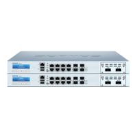
No Bridge Card With Bridge Card
1. Connect the power cord to the AC inlet.
2. Connect the appliance to your LAN via the Network (1) port with an Ethernet cable.
3. Connect the appliance to your laptop or PC via the Config (2) with either an Ethernet cable
or crossover network cable.
4. Press the power button to the right of the LEDs on the front of the unit.
1. Connect the power cord to the AC inlet.
2. Connect the Network(1) port to your LAN, and WAN Connector to your WAN if deploying
in bridged mode. Otherwise just connect Network(1) to LAN.
3. Connect the appliance to your laptop or PC via the Config (2) with either an Ethernet
cable or crossover network cable.
4. Press the power button to the right of the LEDs on the front of the unit.
Network (1) Config (2)
WAN Connector Config (2) Network (1)
 Loading...