18
PROTECTION CIRCUITRY
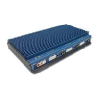
Your REFERENCE405s amplifier is protected against both overheating and
short circuits by means of the following circuits:
• Main power supply fuses
• Circuit breakers on channels 1,2,3 & 4
• Smart Power Supply Thermal Rollback activating at 85°C
• A fail-safe thermal protection circuit activating at 95°C.
Your amplifier also incorporates an innovative Fault Diagnosis system that
identifies a blown power supply fuse.
NOTE: If you experience blown main power supply fuses, DO NOT increase
values beyond the original fuse value! Doing so will void your warranty and
TROUBLESHOOTING
PROBLEM CAUSE
No sound and LEDs
are not lit
• no power or ground at amp
• no remote turn-on signal
• blown fuse near battery
Fault LED is lit
• amp power supply fuse is blown or missing
Repeatedly blown
amp fuse, frequent
activation of Smart
Power Supply Circuit
• check speaker configuration, amp may be in
“High Power” mode, put amp into “High Cur-
rent” mode if speaker load is less than 1 ohm
(see p.8, “Setting High Power/High Current
Switch”)
• speaker or leads may be shorted
• verify adequate amplifier ventilation
Channels 1,2,3 or 4
experiencing inter-
mittent output
• activation of the internal circuit breakers.
• check to make sure channels 1-4 are driving a
2 ohm per channel load or greater
• speaker or leads may be shorted
SERVICE
Your Soundstream REFERENCE405s amplifier is protected by a limited
warranty. Please read the enclosed warranty card.
3
TABLE OF CONTENTS
Design Features ................................................................. 4 - 5
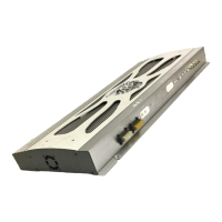
REFERENCE405s Diagram ............................................... 6 - 7
Setting the High Power / High Current Switch ......................... 8
Selecting Input Modes ............................................................. 9
Wiring & Wiring Diagram ................................................ 10 - 11
Installation and Mounting ...................................................... 12
Level Setting ......................................................................... 13
Crossover Adjustments ......................................................... 14
AIRBASS™ ........................................................................... 14
System Installation Diagrams .......................................... 15 -17
Protection Circuitry ................................................................ 18
Troubleshooting .................................................................... 18
Service .................................................................................. 18
Specifications ........................................................................ 19