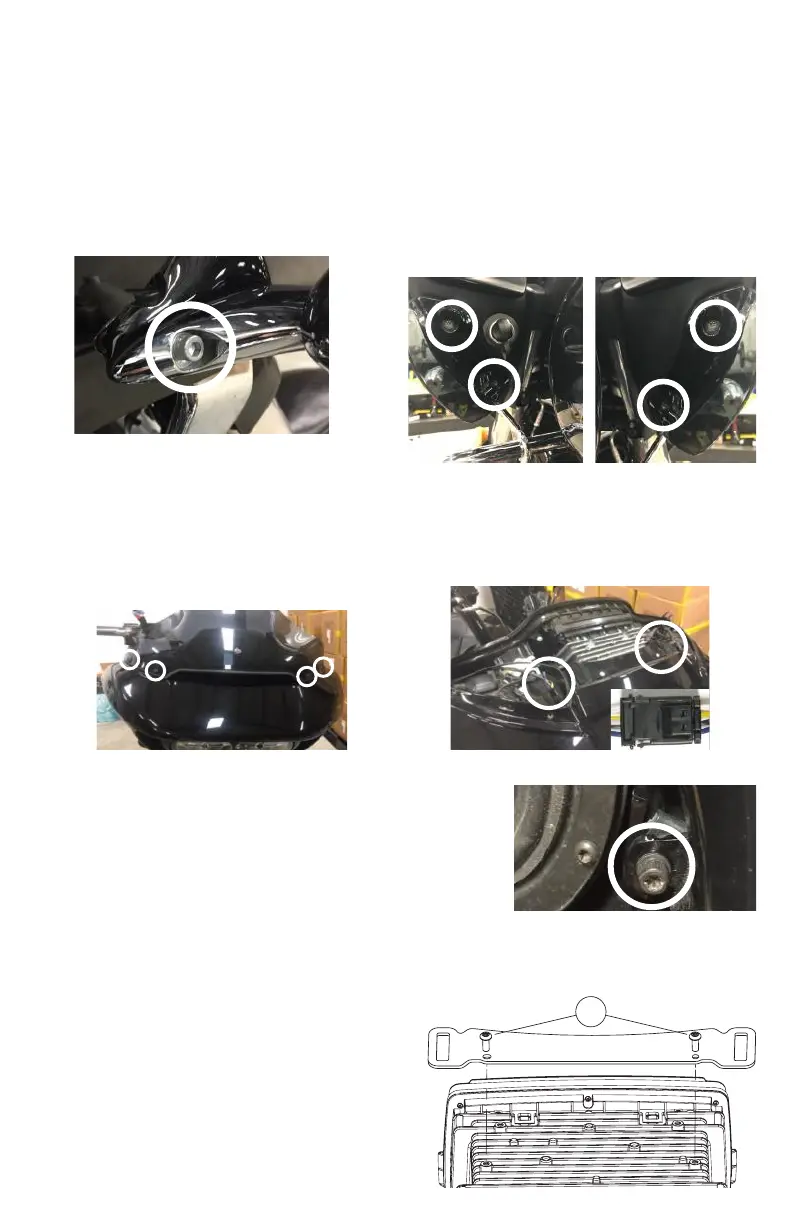
1. Detach each turn signal / indicator light by
removing the adjacent allen socket screw, using
a 3/16” allen head driver. Store these screws in a
safe place for re-installation later.
3. Remove four windshield bolts using a 1/8” allen
driver or Phillips screw driver and remove the
windshield. Also remove factory vent by pulling
straight up on the vent. The vent comes snapped
in place. Store the screws in a safe place for
installation later.
2. Remove four inner fairing bolts using a T25
Torx driver. Two inner fairing bolts are located
below each glove box, adjacent to each wind
deector. Store these screws in a safe place for
installation later.
4. After removing the vent, locate and unplug the
3-pin wire harness for the left and right side turn
signal indicator. These harness’ are adjacent to
each side of the head unit.
REMOVAL OF ORIGINAL HEAD UNIT
ROAD GLIDE
To prevent accidental vehicle start-up, which could cause death or serious injury,
remove main fuse/battery cables before proceeding.
5. Remove an additional inner fairing bolt with a T27 Torx or 5/32”
allen driver, one behind each speaker grill. Remove the speaker
grill by wedging a plastic/nylon pry tool between the inner fairing
and grill edge, popping it outward. Once these bolts are removed,
the outer fairing will be detached from the inner fairing. Store
these screws in a safe place for installation later.
6. While straddling the front wheel fender, grasp the
outer fairing. Gently pull the fairing apart from the
bike. With the fairing slightly pulled away from the
bike, disconnect wire harness for the headlamp or
any other accessories. Lay the fairing on a protected
at surface to prevent damage.
7. Remove two upper support bracket screws using a
3/16” allen driver. Store the bracket and screws in a
safe place for re-installation later.
2