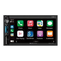
4. If an alternative handlebar integration module other than Scosche is available, skip this step and
proceed to step 5. If included, connect the Scosche handlebar integration module to the corresponding
12-pin and 14-pin connectors on the wire harness of HDHU.14.
5. If an alternative handlebar integration module is available, cut the wires leading to the 12-pin and
14-pin connectors and discard them. Follow the color coded call-out below to connect the wires of
HDHU.14 wire harness to the corresponding inputs and outputs of the alternate handlebar control
module.
14-Pin Connector
Red..........................ACC turn-on
Orange....................Illumination
Violet/White.............CAN -
Green/White............CAN +
Black.......................Ground
Yellow......................12V
12-Pin Connector
Black/White..............Key/SWC Ground
Green/White.............Key/SWC 1
Grey/White...............Key/SWC 2
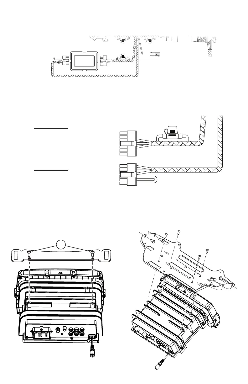
6. Double check all connections are complete and secure. Reassemble the fairing support bracket
using the original screws to the corresponding screw holes on top of HDHU.14. Then, reassemble the
fairing by reversing the model specic instructions covered in REMOVAL OF ORIGINAL HEAD UNIT.
S
COSCHE
2
ROAD GLIDE
STREET GLIDE