5
Electrical Shock Hazard:
• Do not modify the plug provided with the tool.
• Connect this tool to a grounded receptacle on a 20 amp ground fault protected circuit.
Failure to observe these warnings could result in severe injury or death.
This tool must be grounded. In the event of a malfunction or breakdown,
an electrical ground provides a path of least resistance for the electric current.
This path of least resistance is intended to reduce the risk of electric shock.
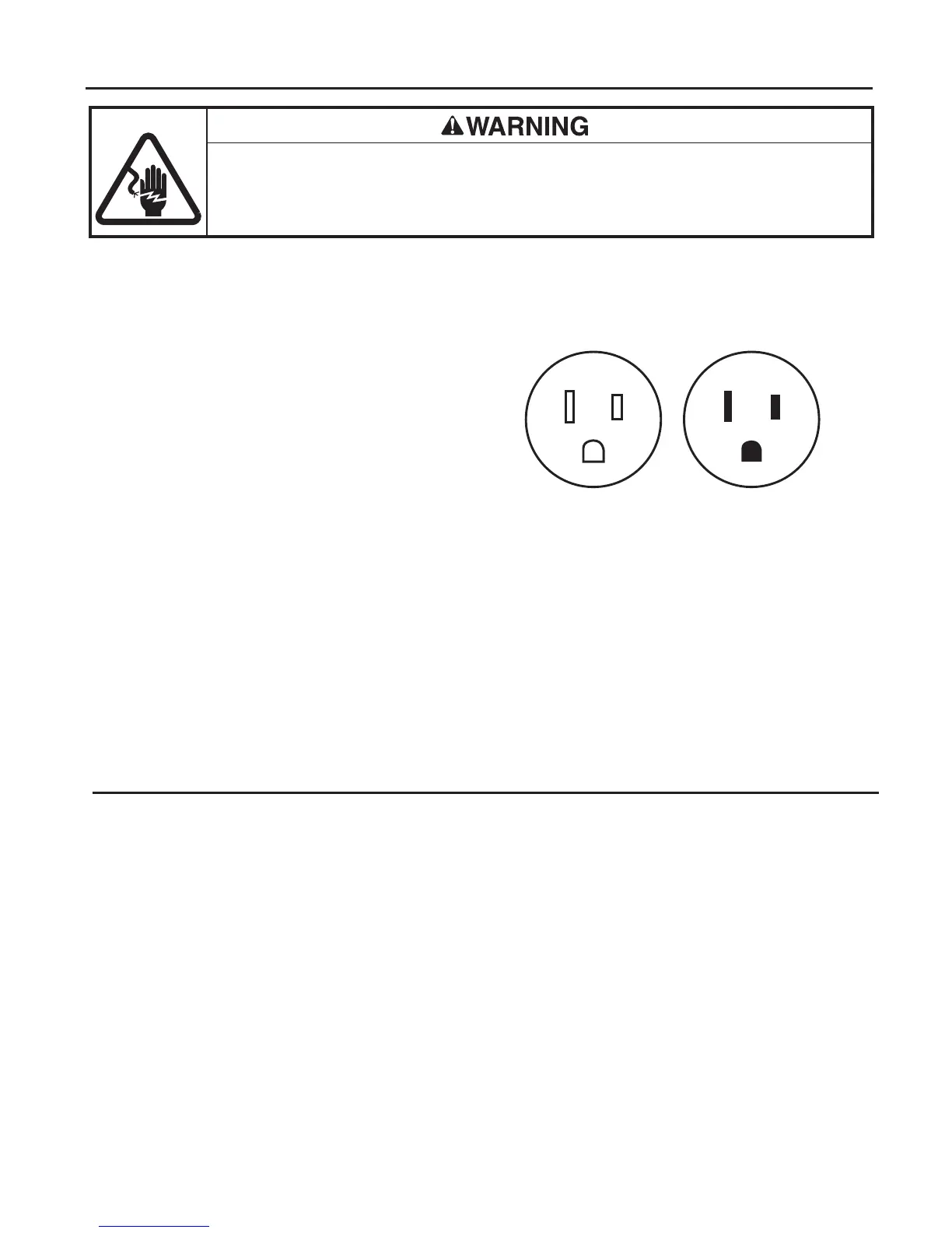
This tool’s electric cord has a grounding conductor and a grounding plug as
shown. Do not modify the plug.
Connect the plug to a corresponding
receptacle that is properly installed and
grounded in accordance with all national
and local codes and ordinances.
Do not use an adapter.
Do not modify the plug provided. If it will not fit the outlet, have the proper
outlet installed by a qualified electrician. Improper connection of the
equipment-grounding conductor can result in a risk of electric shock.
The conductor with insulation having an outer surface that is green with or
without yellow stripes is the equipment-grounding conductor. If repair or
replacement of the electric cord or plug is necessary, do not connect the
equipment-grounding conductor to a live terminal.
Check with a qualified electrician or service personnel if the grounding
instructions are not completely understood, or if in doubt as to whether
the tool is properly grounded.
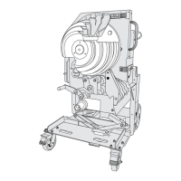
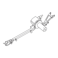
IDENTIFICATION (See Front and Back Views on Page 6)
1. 3/4”- 2” EMT, IMC, Rigid Bending Shoe
2. Bending Hooks (EMT-Gray)
(IMC, Rigid-Black)
3. Analog Protractor
4. Zero and Spring back Setup
5. Digital Display
6. Bender Support Handle
7. 3/4”- 2” Rollers
8. Elevation Travel Indicator
9. Elevation Control Screw Jack
10. Elevation Control Screw Handle
11. Fork Tube
12. Squeeze Adjustment Knob
13. Roller Assembly Lock handle
14. 1
1
/2”- 2” EMT and IMC Roller
15. Locking Tilt Handle
16. Power Receptacle
17. Hand Pendent
18. Pendent Control Cable
19. 15 Amp Fuse
20. Power Switch
21. Push Cart Handle
22. Motor
23. Conduit Support Stand
24. Gearbox
25. Wheel
26. Caster
27. Caster Brake
28. 2 Degree Fine Adjustment Handle
GROUNDING INSTRUCTIONS