65SC-CF & SC-MP Service Manual
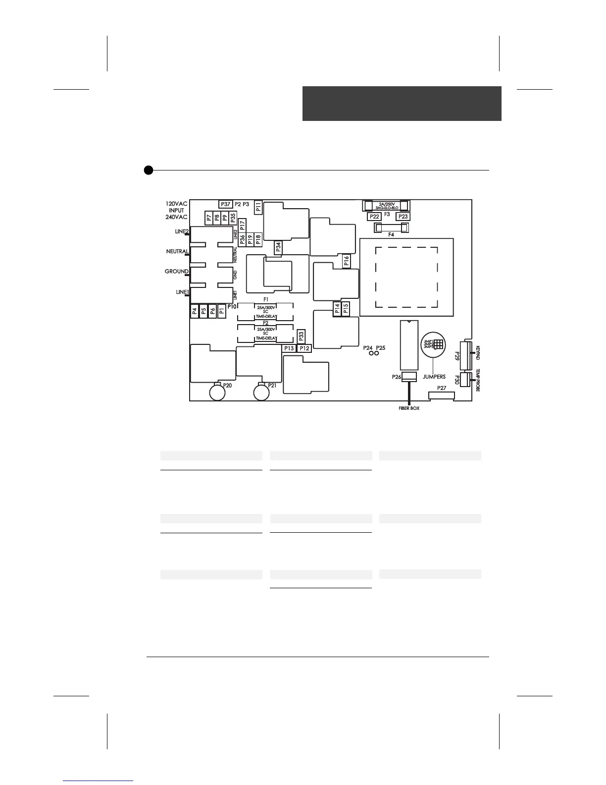
Wiring Diagram (SC-MP)
Pump 1
Voltage 120v 240v
Green / Ground P4 P4
Black / Low Speed P14 P14
Red / High Speed P12 P12
White / Com P7 P18
Pump 2
Voltage 120v 240v
Green / Ground P6 P6
Black / Line P11 P11
White / Com P9 P17
Jumper Settings
Refer to page 10
Light Connector
White / Light P23
Black / 12 VAC P22
Heater
Black 1 P20
Black 2 P21
Pressure Switch
Green P24
Red P25
Ozonator
Voltage 120v 240v
Green / Ground P5 P5
Black / Line P16 P16
White / Com P8 P19
Blower
Voltage 120v 240v
Green / Ground P37 P37
Black / Line P34 P34
White / Com P35 P36
Fiber Box
Voltage 120v
Green / Ground P1
Black / Line P33
White / Neutral P35
The wiring diagram below provides a general idea of SC-MP wiring, but it is important to
note that it may not apply to all systems. The wiring diagram including on inside power
box cover is the one to be used as main reference for the spa you are servicing.