LAHP2-1018
45W30-WG0773
IN UNITED STATES: 260 NORTH ELM ST. WESTFIELD, MA 01085 800-465-8558 / FAX (413) 564-5815
IN CANADA: 7555 TRANMERE DRIVE, MISSISSAUGA, ONTARIO, L5S 1L4 (905) 670-5888 / FAX (905) 670-5782
SECTION 1: READ BEFORE PROCEEDING
Model LAHP Overview ....................................................................... 2
SECTION 2: LAHP FIELD ADJUSTABLE PARAMETERS ... 3-7
SECTION 3: SPECIFICATIONS AND RATINGS ...................... 8-10
SECTION 4: DIMENSIONS ............................................................ 11
SECTION 5: LOCATION & MOUNTING
Prepare the Unit .................................................................................. 12
Location ............................................................................................... 12
Hoisting ................................................................................................ 12
Mounting Pad ...................................................................................... 12
Indoor Installation ................................................................................ 13
SECTION 6: RECOMMENDED PIPING .................................... 13
SECTION 7: GLYCOL/WATER SYSTEM
Glycol/Water System Design/ Installation .......................................... 14-15
SECTION 8: START-UP AND TEST
Preparing for Start-Up ......................................................................... 15
BEFORE Starting the Unit .................................................................. 16
Start the SpacePak Low Ambient Heat Pump .................................. 16
Anti-freeze Cycle ................................................................................. 16
24-Hour follow-up ................................................................................ 16
SECTION 9: ELECTRICAL DIAGRAMS
Pictorial Diagram ................................................................................. 17
Ladder Diagram .................................................................................. 18
Field Connections ............................................................................... 19-20
SECTION 10: TROUBLESHOOTING/FAULT CODES........... 21-22
SECTION 11: MAINTENANCE
Annual Inspection ............................................................................... 23
Preparing the LAHP for Shut Down ................................................... 23
To Restart After Shutdown .................................................................. 23
SECTION 12: REPLACEMENT PARTS ..................................... 24
SECTION 13: LIMITED WARRANTY .......................................... 25
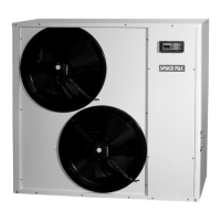
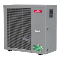
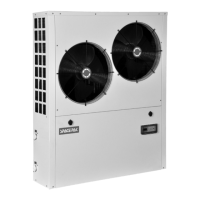
MODEL LAHP48
INSTALLATION,
OPERATION
& MAINTENANCE
MANUAL
Low Ambient Air-to-Water
Reverse Cycle Heat Pump
Copyright 2017 Mestek, Inc.