Assemble the Upper Elevator
25
H
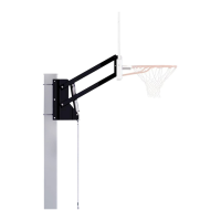
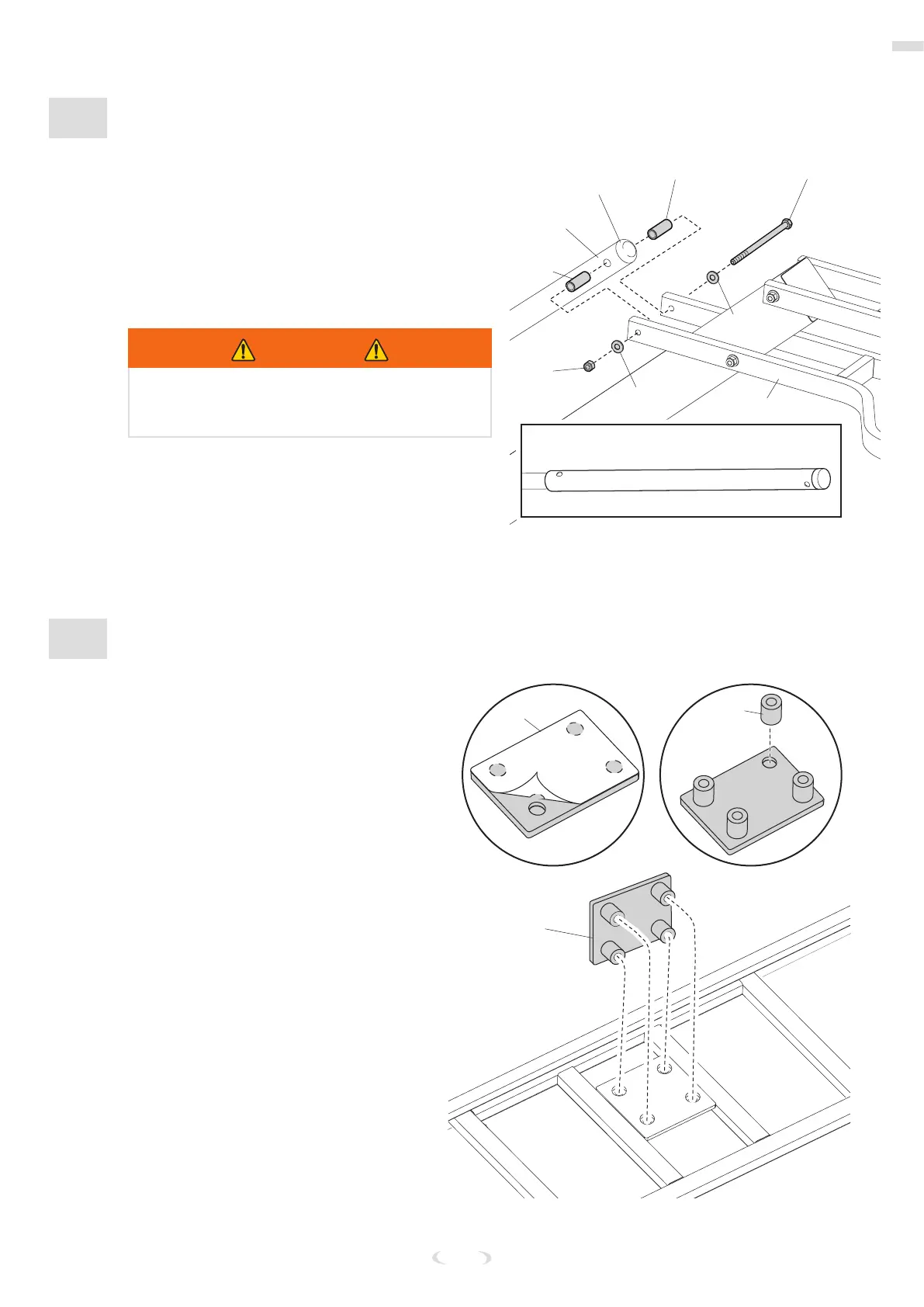
ATTACH THE ELEVATOR TUBE ASSEMBLY
3. While the system is securely resting on the
sawhorse, align the inner metal screw jack
(17) bolt holes with the outer plastic screw
jack sleeve (18) bolt holes.
4. Install the screw jack assembly to the
lower elevator tube (22) using the bolt (A5),
washers (A3), spacers (A7), and nut (A2).
5. Reinstall the screw jack cap (19).
WARNING
TIGHTEN THE BOLT (A5) IN THE LOCK NUT (A2)
UNTIL FLUSH (EVEN) WITH THE LOCK NUT’S
OUTER EDGE.
#18
#19
#A5
#A7
#22
#A3
(Sleeve Rear)
#A3
#A2
#A7
I
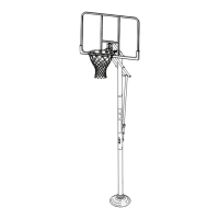
ATTACH THE BACKBOARD
1. Place the foam pad (26) on a at
surface with the adhesive side facing
up and remove protective lm.
2. Align each of the steel spacers (25)
with the four holes in the foam pad
(26) and press the spacers rmly onto
the adhesive of the foam pad.
3. Align the steel spacers on the foam
pad assembly into the mounting holes
on the backboard and rmly press
into position.
#26
#26
#25