13
I
7 IMPIANTI
7.1 SCHEMA A BLOCCHI
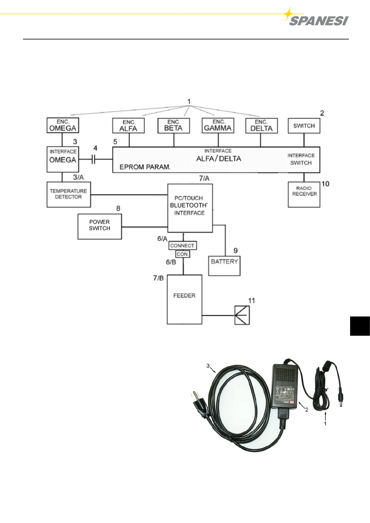
Lo schema funzionale dell’impianto elettrico del TOUCH compreso del braccio misuratore, si compone di un circuito
costituito essenzialmente da (g.5):
TOUCH / A03
Pag. 19 di 28 DC001630
Figura 5 BLOCK DIAGRAM
1. Encoder assi Alfa, Beta, Gamma, Delta, e Omega;
2. Interruttore monostabile normalmente aperto;
3. Schede acquisizione dati encoder- asse omega
3/A. Rilevatore di temperatura
4. Distributore rotante ad anelli;
5. Scheda acquisizione dati encoder assi Alfa-
Beta-Gamma- Delta + acquisizione pulsante +
memorizzazione parametri
6/A. Connettore maschio lato braccio;
6/B. Alimentatore interfaccia con connettore 18 V DC
femmina;
7/A. Interfaccia trasmissione;
7/B. Alimentatore;
8. Interruttore
9. Batteria
10. Ricevitore radio
11. Spina elettrica.
Fig. 5
TOUCH / A03
Pag. 23 di 28 DC001630
Key
:
1) 18V DC connector
2) Automatic selection feeder 100-240V 50/60 Hz
3) Cable of net supplying
Figure 7 POWER SUPPLY
Fig. 5/A: Particolare Alimentatore interfaccia
Legenda:
1. Connettore da 18 V DC
2. Alimentatore 100-240 V 50/60 Hz selezione
automatica
3. Cavo alimentazione rete
 Loading...