32
GB
7 SYSTEMS
7.1 BLOCK DIAGRAM
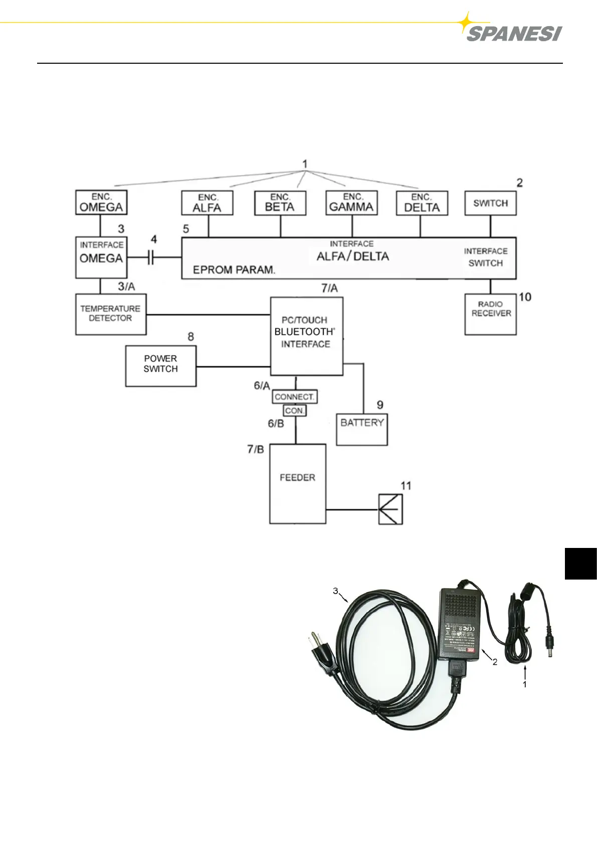
The wiring diagram of the TOUCH unit, including the measuring arm, consists in a circuit essentially made up of (Figure
5):
TOUCH / A03
Pag. 19 di 28 DC001630
Figura 5 BLOCK DIAGRAM
1. Encoder for Alpha, Beta, Gamma, Delta, and Omega
axes;
2. Normally open monostable switch;
3. Encoder data acquisition cards - Omega axe
3/A Temperature detector
4. Ring collector;
5. Encoder data acquisition card Alpha-Beta-Gamma-
Delta axes + button acquisition + parameters
memorization .
6/A. Arm side male connector;
6/B. Feeder interface 18 V DC with female connector ;
7/A. Transmission interface
7/B. Power supply;
8. Power switch
9. Battery
10. Radio receiver
11. Electric plug.
Fig. 5
TOUCH / A03
Pag. 23 di 28 DC001630
Key
:
1) 18V DC connector
2) Automatic selection feeder 100-240V 50/60 Hz
3) Cable of net supplying
Figure 7 POWER SUPPLY
Fig. 5/A: Feeder interface detail
Legend:
1. 18 V DC Connector
2. Feeder 100-240 V 50/60 Hz automatic selection
3. Net power supply cable
 Loading...