92
E
7 INSTALACIONES
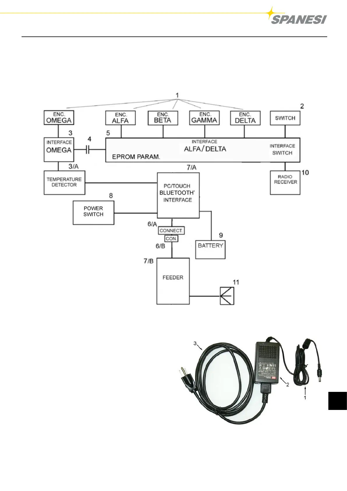
7.1 DIAGRAMA DE BLOQUES
El esquema funcional de la instalación eléctrica de TOUCH incluido en el brazo de medición, está compuesto por un
circuito constituido fundamentalmente por (Fig.5):
TOUCH / A03
Pag. 19 di 28 DC001630
Figura 5 BLOCK DIAGRAM
1. Encoder, ejes Alfa, Beta, Gama, Delta y Omega
2. Interruptor monoestable normalmente abierto;
3. Tarjetas de adquisición de los datos del encoder- eje
Omega;
3/A detector de temperatura
4. Distribuidor rotatorio de anillos;
5. Tarjetas de adquisición de los datos del encoder - eje
Alfa-Beta-Gamma-Delta + adquisición pulsador +
memorización parámetros
6/A. Conector macho lado brazo;
6/B. Cable de conexión brazo-interfaz con conector hembra
18 V DC;
7/A. Interfaz de transmisión
7/B Alimentador
8. Interruptor
9. Batería
10. Radioreceptor
11. Clavija eléctrica
Fig. 5
TOUCH / A03
Pag. 23 di 28 DC001630
Key
:
1) 18V DC connector
2) Automatic selection feeder 100-240V 50/60 Hz
3) Cable of net supplying
Figure 7 POWER SUPPLY
Fig. 5/A: Alimentador interfaz
Leyenda:
1. Conector hembra 18 V DC;
2. Alimentador 100-240 V 50/60 Hz con selección
automática
3. Cable de alimentación de red
 Loading...