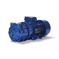
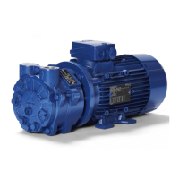
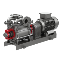
OPERATING INSTRUCTIONS
20
order to avoid a pressure drop in the vacuum
system.
CAUTION
If a shut-off device (sliding valve or similar) is
fitted in the suction pipe and if the pump
should be commissioned, when this shut-off
device is closed, cavitation will occur. This will
destroy pump material during a longer working
period.
15.3.2 Discharge Pipes
If in the discharge pipe or in the discharge pipe
of the liquid separator a shut-off device is
installed, it has to be taken care that the pump
will not be operated or kept running while the
shut-off device is closed.
15.4
Electrical connection
Electrical connection of the pump must be
carried out by skilled personnel only!
The connecting diagramm of the motors is
shown inside the terminal box cover.
Apart from the faultless electrical installation
required (taking into account appropriate
guidelines and VDE regulations), serious
consideration is necessary of the pump's direction
of rotation (flow direction), which is shown by an
arrow on the pump casing.
The electric motor always needs a protective
motor switch (except for versions with coil
protection contacts or posistors, serving for the
direct motor switch-off). Operating without a
protective motor switch on the input side that is
properly set (at a rated current of I
N)
shall
invalidate any claims for compensation of
damages. The rotating direction of the shaft as
well as the flow direction of the gas is marked
by arrows at the pump casing.
CAUTION
In order to avoid any damages at the
mechanical seal, the pump shaft may not
be operated in anti-clockwise direction for
a longer period.
15.5
Operation modes
15.5.1 Open circulation cooling
(standard operation under normal conditions)
The setting up is per illustr. 2a. The operating
liquid B consists of clean liquid F and
circulating liquid U. Liquid similar to clean
liquid F added, leaves the liquid separator as
discharge liquid A through the liquid discharge
U
A
. The pressure of clean liquid should exceed
max. 0,2 bar the pressure at the pump
discharge nozzle resp. in the liquid separator.
15.5.2 Closed circulation cooling
The closed circulation cooling is applied for
operating liquids, which have due to their
characteristics to remain in the circulatory
process or which may not get in touch with the
cooling medium, or where corrosive ,
hazardous or highly combustible gases are
delivered.
The setting up is per illustr. 3. At connection U
A
a shut-off device will be attached. The
operating liquid B consists of circulation liquid
U. In the circulating pipe I
U
, a liquid ring
vacuum pump P
B
has to be mounted, if the
vacuum pump is running more than 5 minutes
without considerable pressure difference
between suction and discharge nozzle.
The heat exchanger W has to be dissipate
about 85 % of the motor power and possibly
arising condensation heat. The heat exchanger
W may be omitted, if the vacuum pump will be
run only a few minutes and if the liquid in the
system cools down to ambient temperature
during the period before it is used next.
15.5.3 Continuous cooling
The continuous cooling is effected, if sufficient
liquid is available, for which it is not important
being recycled as operating liquid.
The setting up is to be effected according to
illustr. 4a. The connection U
U
will be sealed.
The operating liquid B consists of clean liquid
F. The required pressure of clean liquid should
not considerably exceed 0 bar (atmospherical
pressure).
If the pressure of clean liquid is considerably
fluctuating (from time to time an over pressure
of 0,2 bar will be exceeded), it is useful to
provide a pressure reducing valve R
F3
(illustr.
2b) or to lead the clean liquid into a container b
with float valve R
F1
. The pump primes the
operating liquid B out of this container (illustr.
4b). The level of the liquid should be in the
middle of the shaft.
In case the gas and the liquid have not to be
discharged separately, a liquid separator may
be omitted. It would then be sufficient to install
a pipe I
D
, leading to a discharge sink.