EasyManua.ls Logo

Spectrum Controls Micro800 Series - Minimum Spacing; Parts List; Module Description

Default Icon
40 pages
Print Icon
To Next Page IconTo Next Page
To Previous Page IconTo Previous Page
Loading...
2-4 Chapter 2: Installation and Wiring
User’s Manual Pub. 0300309-01 Rev. A
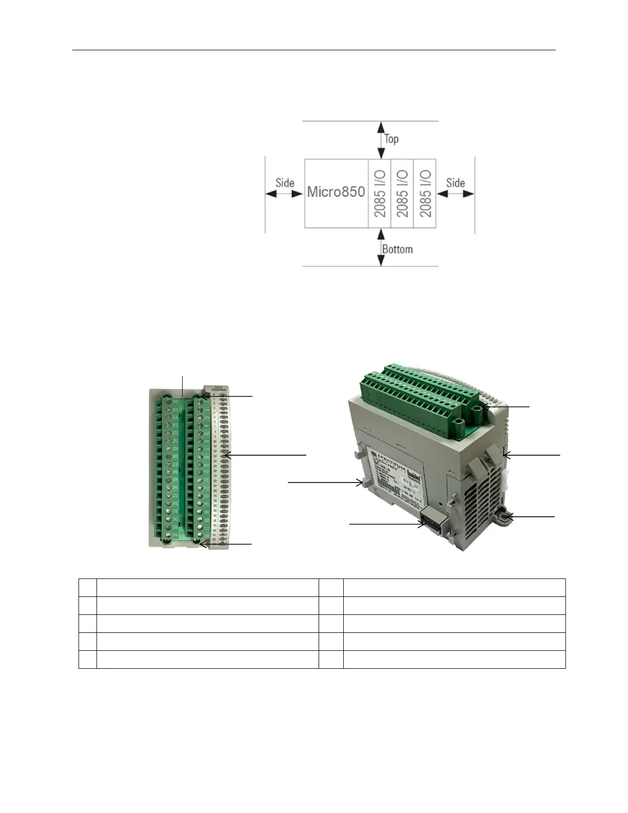
2.3.1 Minimum Spacing
Maintain spacing from enclosure walls, wire ways, adjacent equipment, etc.
Allow 50.8 mm (2 in.) of space on all sides for adequate ventilation, as shown:
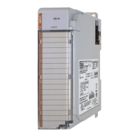
2.3.2 Parts List
Your package contains one Micro800 Expansion I/O 2085-OX32-SC Module and
one Quick Start Guide.
2.3.3 Module Description
Description
Description
1
Mounting screw hole/mounting foot
5
DIN rail mounting latch
2
Removable Terminal Block (RTB)
6
I/O Status LEDs
3
RTB hold down screws
7
Bus Connector (2, Right and Left)
4
Module interconnect latch
3
5
1
2
4
3
3
6
7

Related product manuals