滚滚长江东逝水
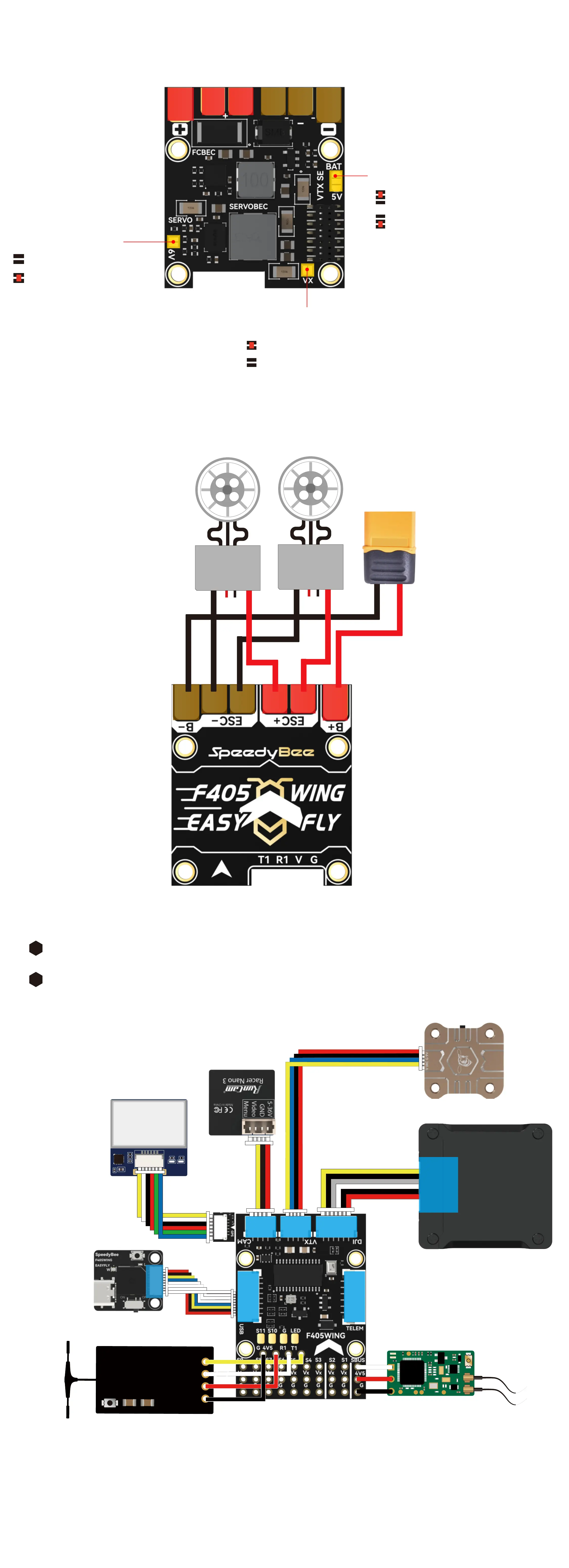
PDB Board Back
PDB Board Front
Default 5V Output
6V Output
ESC BEC power supply
Default seo BEC power supply
Seo BEC
Voltage Jumper
Seo BEC Power
Supply Jumper
VTX Power Supply Jumper
Default batte voltage output
5V Output
Selecting the 6V BEC voltage for seo
will raise Vv's 5V output to 6V. When
using batte voltage output, ensure
that the VTX suppos a wide voltage
range of 7-26V to prevent damage.
pps
T R G VC D
TX
FC Board Front
BZ-251 GPS
The pin order on the
GPS solder pads diers
from the GPS inteace
CH2 R
X
CH1 T
X
5V
GND
SBUS/PPM receiver
HD VTX
ELRS/TBS receiver
FPV CAM
Analog VTX
GPS Module
Use a 4-pin Dupont female
header on the FC Board front.
Use a 3-pin Dupont female
header on the FC Board front.
CAM2
CAM1
GND
Vv
RX6
BOOT0
BZ-
TX6
D+
D-
GND
4V5
4V5
TX4
RX4
TX2
RX2
GND
VTX
TX5
GND
Vv
SBUS
GND
RX5
TX5
GND
Vv
4V5
GND
D-
D+
TX6
BZ-
BOOT0
RX6
HDL
GND
TX
RX
GND
POWER
ESC
ESC
Peripheral Connection on FC Board
Method 1, Plug and Play