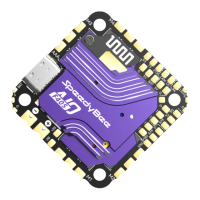
Product Name SpeedyBee F405 WING MINI PDB board
SpeedyBee F405 WING MINI PDB board
Input voltage range 7~26V (2~6S LiPo)
Battery Voltage Sensor
Connect to FC board VBAT, 1K:10K (Scale 1100 in INAV, BATT_VOLT_MULT 11.0 in
ArduPilot)
Battery Current Sensor
80A continuous, 150A peak Connect to FC board Current (Scale 195 in INAV, 50 A/V
in ArduPilot)
TVS Protective diode Yes
FC BEC output
Output 5.2V +/- 0.1V DC Continuous current 2 Amps, 3A Peak Designed for FC,
Receiver, GPS module, AirSpeed Sensor, Telemetry module
VTX & Camera power supply
The VTX power interface Vv offers two power supply options: direct battery voltage
or integrated BEC 5V (sharing the 5V4A Servo BEC voltage)
By default, it is set to battery voltage
(Ensure the VTX and camera input voltage range is compatible)
Switching to 5V power supply is possible via pad jumper (using Servo BEC output)
(If using this method, ensure the current requirements for both servo and VTX are
sufficient)
Servo BEC output
Output 5V +/- 0.1V DC Continuous current 4 Amps, 5A Peak Voltage adjustable, 5V
Default, 6V via jumper Designed for Servos.
Weight 5.5g
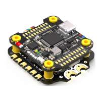
Product Name SpeedyBee F405 WING MINI W
SpeedyBee F405 WING MINI Wireless USB Extender
ireless USB Extender
Wireless Configuration (long press
BOOT button for 6 seconds to
switch modes)
INAV:Please make sure the MSP
switch on UART 6 is turned on and
set to a baud rate of 115200
ArduPilot:Please make sure the
Serial 6 is set to baud rate 115200
and protocol Mavlink2
BLE mode, connect to Speedybee APP
Wi-Fi (AP)mode, able to connect to Speedybee APP, QGroundControl APP,
MissionPlanner, etc. WiFi: Speedybee eFLY-WIFI Password: 88888888
Wi-Fi (STA)mode, able to connect to QGroundControl APP, MissionPlanner, etc.
Step 1: turn on Personal Hotspot;
Step 2: Set hotspot, locate NAME/Device Name/Hotspot name/etc.
Step 3: change the current name to eFLY and the password is, 88888888
Wireless off mode
USB Port Type Type-C
Buzzer 5V Active Buzzer
Weight 3.2g
Pa5-pin mapping
UART
USB
TX1 RX1 5V tolerant I/O UART1 ELRS/TBS receiver
TX2 RX2
SBUS
5V tolerant I/O
SBUS pad
TX2
USB
INAV mapping
PWM TIMER INAV Plane INAV MultiRotor
S1 TIM4_CH2 Motor Motor
5V tolerant I/O
S2 TIM4_CH1 Motor Motor
5V tolerant I/O
S3 TIM3_CH3 Seo Motor
5V tolerant I/O
S4 TIM3_CH4 Seo Motor
5V tolerant I/O
S5 TIM8_CH3 Seo Motor
5V tolerant I/O
S6 TIM8_CH4 Seo Motor
5V tolerant I/O
S7 TIM8_CH2N Seo Seo
5V tolerant I/O
S8 TIM2_CH1 Seo Seo
5V tolerant I/O
S9 TIM2_CH3 Seo Seo
5V tolerant I/O
S10 TIM2_CH4 Seo Seo
5V tolerant I/O
S11 TIM12_CH2 Seo Seo
5V tolerant I/O
LED
TIM1_CH1 WS2812LED WS2812LED
5V tolerant I/O
Open "Conguration" tab, scroll to "Other Features",
enable "Multi-color RGB LED strip suppo", save and reboot.
In "Led Strip" tab of INAV GUI, congure LED colors and behaviors , then save.
ADC
VBAT
CURR
AIRSPD
RSSI
VBAT ADC
ADC_CHANNEL_1
CURRENT_METER ADC
ADC_CHANNEL_2
AIRSPEED ADC
ADC_CHANNEL_3
RSSI ADC
ADC_CHANNEL_4
voltage scale 1100
1K:10K divider builtin
0~30V
0~3.3V
10K:10K divider builtin
0~6.6V
0~3.3V
Current scale 195
Analog Airspeed
Analog RSSI
I2C
I2C1
onboard Barometer
Compass
Digital Airspeed sensor
OLED
SPL06-001
QMC5883 / HMC5883 /
MAG3110 / LIS3MDL
MS4525
0.96″
5V tolerant I/O
ArduPilot mapping
USB
TX1 RX1
TX2 RX2
SBUS
TX3 RX3
TX4 RX4
TX5 RX5
TX6 RX6
USB
USART1(With DMA)
SBUS pad
RX2
USART2
USART3
UART4
UART5
USART6
SERIAL0
SERIAL1
BRD_ALT_CONFIG 0
Default
BRD_ALT_CONFIG 1
SERIAL2
SERIAL3
SERIAL4
SERIAL5
SERIAL6
Console
ELRS/TBS receiver
Serial RC input
SBUS receiver,
SBUS pad = RX2 with inveer
IBUS/DSM/PPM
USER
GPS1
USER
DJI OSD/VTX
Telem1
*If sending highspeed serial data (eg. 921600 baud) to the board, use USART1(Serial1).
PWM
S1
S2
S3
S4
S5
S6
S7
S8
S9
S10
S11
LED
PWM1 GPIO50
PWM2 GPIO51
PWM3 GPIO52
PWM4 GPIO53
PWM5 GPIO54
PWM6 GPIO55
PWM7 GPIO56
PWM8 GPIO57
PWM9 GPIO58
PWM10 GPIO59
PWM11 GPIO60
PWM12 GPIO61
TIMER
TIM4_CH2
TIM4_CH1
TIM3_CH3
TIM3_CH4
TIM8_CH3
TIM8_CH4
TIM8_CH2N
TIM2_CH1
TIM2_CH3
TIM2_CH4
TIM1_CH3N
TIM1_CH1
PWM/DShot(DMA)
PWM/DShot(DMA)
PWM/DShot(DMA)
PWM/DShot(DMA)
PWM/DShot(DMA)
PWM/DShot(DMA)
PWM/DShot(DMA)
PWM/DShot(DMA)
PWM/DShot(DMA)
PWM/DShot(DMA)
PWM/DShot(DMA)
PWM/DShot(DMA)
Group1
Group2
Group3
Group4
Group5
*All motor/seo outputs are DShot and PWM capable. However, mixing DShot and normal PWM operation
for outputs is restricted into groups, ie. enabling DShot for an output in a group requires that ALL outputs
in that group be congured and used as DShot, rather than PWM outputs. LED, which corresponds to
PWM12, is set as the default output for NeoPixel1. Therefore, if you need to use PWM11 as an output,
you need to disable the NeoPixel1 function on PWM12.
ADC
VBAT
CURR
AIRSPD
RSSI
Batte voltage
Current sense
Analog Airspeed
Analog RSSI
BATT_VOLT_PIN
BATT_VOLT_MULT
BATT_CURR_PIN
BATT_AMP_PERVLT
ARSPD_ANA_PIN
ARSPD_TYPE
RSSI_ANA_PIN
RSSI_TYPE
10
11.05
11
50
15
2
14
2
1K:10K divider builtin
0~30V
0~3.3V
10K:10K divider builtin
0~6.6V
0~3.3V
I2C
I2C1
onboard Barometer
Compass
Digital Airspeed sensor
MS4525
ASP5033
SPL06-001
COMPASS_AUTODEC
ARSPD_BUS
ARSPD_TYPE
ARSPD_TYPE
0
1
15
5V tolerant I/O
TX3 RX3 5V tolerant I/O UART3
TX4 RX4 5V tolerant I/O UART4
TX5 RX5 5V tolerant I/O UART5
TX6 RX6 5V tolerant I/O UART6
GPS
USER
DJI OSD/VTX
Onboard wireless controller
SmaPo
Open "Conguration" tab, scroll to
"Other Features",enable "CPU based serial pos",
save and reboot.
In "Pos" tab, select "SOFTSERIAL2",
set telemet to "SmaPo", save and reboot.
SBUS receiver, SBUS pad = RX2 with inveer
 Loading...