EasyManua.ls Logo

SpeedyBee Master 5 V2 - User Manual

SpeedyBee Master 5 V2
12 pages
Print Icon
To Next Page IconTo Next Page
Loading...
* (Note: 3D eect requirements, the actual object shall prevail)
Question and Answer IconNeed help?

Do you have a question about the SpeedyBee Master 5 V2 and is the answer not in the manual?

Summary

Master 5 V2 Installation Guidelines

CNC Camera Mount and Side Plate Installation

Install the CNC camera mount and camera side plate using provided hardware.

Antenna Installation Sequence

Secure the antenna by inserting the O-ring onto the TPU antenna base.

Multi-function Antenna Base Installation

VTX Antenna Base and GPS Base Assembly

Install the VTX antenna base and GPS installation base onto the frame.

Arms and Anti-vibration Module Installation

Arm and Anti-vibration Module Mounting

Mount the front and back arms, and install the anti-vibration stack module.

Middle Plate Installation

Install Middle Plate and Tighten Nuts

Attach the middle plate and secure the intersecting arm points with press-in nuts.

Frame and Component Combination

Combine Frame, Mounts, and Standoffs

Combine previously assembled parts, install 7075 standoffs, and attach bottom protection silicone.

Rear Top Plate and Battery Silicone Installation

Install Rear Top Plate and Battery Silicone

Attach the rear top plate and battery anti-slip silicone for protection.

Arm Foot Mount Installation

Install 3 D Printed Foot Mounts

Mount the 3D printed foot mounts to the arms using appropriate screw lengths.

O3 Air Unit Installation

Mount O3 Air Unit VTX and Heat Sink

Install the O3 Air Unit VTX onto the frame's heat sink using specified screws.

ESC Reverse Installation and Cable Management

ESC Orientation and Cable Length Guidance

Recommended ESC installation orientation and main power cable length guidance.

ESC Wiring and Motor Cable Lengths

ESC Soldering and Motor Wire Lengths

Details on ESC power cable soldering and recommended motor wire lengths for inner and outer routing.

Overview

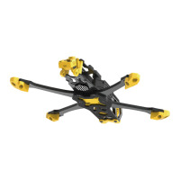
The provided document is an installation guideline for the "Master 5 V2" drone frame, focusing on the assembly process rather than a comprehensive device description. Based on the installation steps, here's a description of the device:

The Master 5 V2 is a drone frame designed for FPV (First Person View) racing and freestyle flying, emphasizing a robust and modular construction. It features a predominantly black carbon fiber frame with distinctive yellow TPU (Thermoplastic Polyurethane) parts for protection and mounting. The frame is designed to accommodate various electronic components, including a flight controller, ESC (Electronic Speed Controller), motors, camera, VTX (Video Transmitter), GPS module, and an O3 Air Unit.

Function Description:

The Master 5 V2 serves as the structural backbone for a DIY FPV drone. Its primary function is to securely house and protect all necessary electronic components while providing a lightweight yet durable platform for flight. The modular design allows for customization and easy replacement of parts, catering to both experienced builders and those new to FPV drones. The frame's anti-vibration module aims to reduce vibrations transmitted to sensitive electronics, improving flight performance and video quality.

Important Technical Specifications (derived from installation steps):

  • Frame Material: Primarily carbon fiber for the main plates and arms, combined with TPU for protective and mounting parts.
  • Fasteners:
    • M35, M23 screws for CNC camera mount and side plates.
    • M2.5*8 screws for multi-function antenna base.
    • M3*23 standoff for O3 Air Unit antenna base.
    • M314 and M311 screws for arm installation.
    • M2*8 screws for middle plate installation.
    • M35, M2.56, M3*6 screws for combining frame parts and antenna base.
    • M3*6 screws for rear top plate and battery anti-slip silicone.
    • M38mm and M310mm default screws for arm foot mounts.
    • M1.6*8 screws for O3 Air Unit installation with honeycomb heat sink.
  • GPS Installation Base Size: 18188mm.
  • Battery Anti-slip Silicone Thickness: 2.5mm.
  • Bottom Protection Silicone Thickness: 0.5mm.
  • Recommended Motor Wire Lengths:
    • Inner motor wire: 110mm
    • Outer motor wire: 93mm
  • Recommended ESC Power Cable Length: Approximately 100mm (adjustable based on battery).
  • Standoffs: Includes 7075 standoffs for structural rigidity.

Usage Features:

  • Modular Design: The frame is assembled from distinct parts (front top plate, camera side plates, arms, middle plate, rear top plate, antenna bases, stack protector), allowing for easy assembly, disassembly, and component replacement.
  • Camera Mounting: Features a CNC camera mount and side plates, providing a secure and adjustable platform for FPV cameras.
  • Multi-function Antenna Base: Designed to accommodate various VTX antennas (including SMA) and a GPS module. It also supports the O3 Air Unit antenna.
  • Anti-vibration Module: Integrated into the frame structure to minimize vibrations, which is crucial for stable flight and clear video feed.
  • Component Protection: TPU parts are used for arm foot mounts, antenna bases, and a stack protector, offering impact resistance and cushioning for sensitive electronics.
  • O3 Air Unit Compatibility: Specifically designed with a mounting method for the O3 Air Unit, including a dedicated honeycomb heat sink for efficient cooling.
  • ESC Installation Flexibility: Recommends installing the ESC in reverse horizontally by 180 degrees, with a note to redefine motor directions in the flight controller software.
  • Cable Management: Provides suggestions for main power cable placement and specific motor wire lengths for optimal setup.
  • Buzzer and Capacitor Placement: Dedicated areas are indicated for mounting a capacitor and buzzer, essential for power filtering and drone recovery.

Maintenance Features:

  • Replaceable Parts: The modular nature of the frame means individual components like arms, top plates, or TPU parts can be replaced if damaged, extending the lifespan of the drone.
  • Standardized Fasteners: Utilizes common screw sizes (M2, M2.5, M3, M1.6) for assembly, making it easier to find replacement hardware.
  • Clear Installation Guidelines: The detailed step-by-step instructions with visual aids facilitate assembly and maintenance tasks.
  • QR Code for Guidance: Provides a QR code for an installation guide and the SpeedyBee App, offering accessible support and detailed instructions for users.

The Master 5 V2 frame is a comprehensive solution for building a high-performance FPV drone, offering a balance of durability, modularity, and compatibility with popular FPV components.

SpeedyBee Master 5 V2 Specifications

General IconGeneral
BrandSpeedyBee
ModelMaster 5 V2
CategoryDrones
LanguageEnglish

Related product manuals