EasyManua.ls Logo

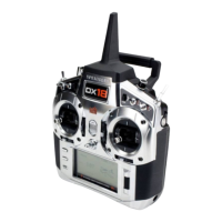
Spektrum DX18 User Manual

Spektrum DX18
42 pages
To Next Page IconTo Next Page
Page #1 background imageLoading...
Page #1 background image
Instruction Manual
Bedienungsanleitung
Manuel d’utilisation
Manuale di Istruzioni
18
18
®
®

Table of Contents

Questions and Answers:

Spektrum DX18 Specifications

General IconGeneral
InterfaceRF Wireless
Input typePress buttons
Product colorSilver
Remote control proper useGame console
Built-in displayYes
Maximum range- m
Frequency band2.4 GHz
Number of devices supported1
Battery capacity2600 mAh
Battery technology-
Weight and Dimensions IconWeight and Dimensions
Weight- g

Summary

TRANSMITTER BATTERIES

Battery and Charging Precautions and Warnings

Crucial safety and charging advice for transmitter batteries to prevent malfunction, electrical issues, fire, or injury.

Charging Your Transmitter

Instructions for charging the internal LiPo battery using the provided power supply and its LED indicators.

LED Indicators

Explanation of the blue and orange LED lights indicating charging status and radio transmission.

Battery Alarm

Description of the audio alarm for low battery voltage and related warnings.

MAIN SCREEN

Model Memory

Displays and allows selection of internal model memory locations for the transmitter.

Model Name

Allows assigning a custom name (up to 20 characters) to the current model memory.

Transmitter Battery Charge Level

Shows the current charge level of the transmitter's internal battery.

Digital Battery Voltage

Displays current voltage with warnings for low levels.

Model Type

Process for selecting and changing aircraft model type, including data reset.

Elevator Trim

Displays and adjusts elevator trim values for specific modes.

Throttle Trim

Displays and adjusts throttle trim values for specific modes.

Aileron Trim

Displays and adjusts aileron trim values for specific modes.

Rudder Trim

Displays and adjusts rudder trim values for specific modes.

Model Memory Timer

Tracks elapsed time for the currently active model memory.

Timer

Manages countdown or stopwatch timers for display on the main screen.

NAVIGATION

Scroll Wheel Operation

Explains how to use the scroll wheel for screen navigation and value changes.

Back Button Usage

Describes using the Back button to return to the previous screen.

Clear Button Functionality

Details how the Clear button resets selected values to their default settings.

Direct Model Access

Enables accessing the Model Select screen without powering off the transmitter.

System Setup Access

Explains how to access the System Setup list by holding the roller while powering on.

BINDING

Binding Using the Receiver and Receiver Battery

Step-by-step guide to binding the receiver to the transmitter using a receiver battery.

Binding Using the Receiver and ESC

Step-by-step guide to binding the receiver to the transmitter using the ESC.

Binding Caution

Warning about using parkflyer receivers in larger aircraft due to potential signal blocking.

PROGRAMMING FAILSAFE POSITIONS

SmartSafe Failsafe

Failsafe that acts only on the throttle channel, preventing motor operation when off.

Hold Last Command

Failsafe that maintains the last command on all channels except throttle if signal is lost.

Preset Failsafe

Failsafe that moves all channels to their programmed failsafe positions.

To Test the SmartSafe

Procedure to test the SmartSafe failsafe functionality.

To Test Hold Last Command

Procedure to test the Hold Last Command failsafe functionality.

X-PLUSTM

X-Plus Channels and Failsafe

Information regarding failsafe support for X-Plus module servos and channel behavior.

To Activate X-Plus

Steps to activate the X-Plus feature via the Frame Rate menu in System Setup.

X-Plus Caution

Warning against connecting throttle or primary control surfaces to the X-Plus Module.

SD CARD

Installing the SD Card

Instructions for physically installing the SD card into the transmitter.

Exporting the Transmitter Serial Number to the SD Card

Steps to export the transmitter's serial number to the SD card for registration.

MODEL TYPE PROGRAMMING GUIDE

Airplane Model Type Programming

Outlines menu options available for Airplane models in System Setup and Function List.

Helicopter Model Type Programming

Outlines menu options available for Helicopter models in System Setup and Function List.

Sailplane Model Type Programming

Outlines menu options available for Sailplane models in System Setup and Function List.

COMMON SYSTEM SETUP FUNCTIONS

System Setup

Overview of the System Setup menu and its main components.

Model Select

Guides on selecting and accessing internal model memory locations.

Direct Model Access

Instructions to access the Model Select screen from the Main or telemetry screen.

Model Type

Process for selecting and changing the aircraft model type, including data reset.

Model Name

Steps to assign a custom name to the current model memory.

F-MODE SETUP

F Mode Setup Overview

Explains how to assign switches to flight modes for aircraft, heli, and sailplane types.

Flight Mode Name Setup

Process to assign custom names to flight mode positions with up to 20 characters.

Channel Assignment

Guides on reassigning receiver channels to different transmitter channels or inputs.

CHANNEL INPUT CONFIGURATION

Channel Input Configuration

Assigning transmitter channels to different control sticks or switches.

X-Plus Input Configuration

Assigning X-Plus channels to any transmitter input.

Trim Setup

Adjusting trim step value and selecting trim type (Common or F Mode).

Trim Assignment

Reassigning trim functions to different locations.

MODEL COPY

Model Copy Functionality

Duplicating model programming from one memory location to another.

MODEL RESET

Model Reset Function

Deleting all model programming in the active memory and resetting to defaults.

WARNINGS MENU

Warnings Menu Functionality

Programming tone or vibration alerts for unsafe switch or control stick positions at power-on.

TELEMETRY

Telemetry Overview

Overview of optional telemetry module and sensors for displaying aircraft data.

Telemetry Settings Display

Options for displaying telemetry alerts on the main screen or enabling full telemetry screens.

PREFLIGHT SETUP

Preflight Setup Menu

Programming a pre-flight checklist that appears upon transmitter power-on.

FRAME RATE OPTIONS

Frame Rate Menu

Changing frame rate, modulation mode, and activating XPLUS.

Modulation Mode

Recommended use of DSMX modulation and its automatic detection.

X-Plus Activation

Activating X-Plus channels via the Frame Rate screen.

BIND FUNCTION

Bind Functionality

Binding a transmitter and receiver without powering off the transmitter.

TRAINER

Trainer Modes

Describes the 4 programmable trainer modes: Inhibit, Programmable, Pilot Link Master, Slave.

DX18 Trainer Operation

Step-by-step guide for operating the trainer function with a cord.

Analog Switch Setup

Using sticks and pots as kick points to activate functions like mixes.

SYSTEM SETTINGS

User Name Configuration

Steps to program and display a user name on the main screen.

Contrast Adjustment

Adjusting the screen contrast for better visibility.

Backlight Settings

Adjusting backlight appearance time and brightness.

Mode Conversion

Notes on changing control stick modes (e.g., Mode 2 to Mode 4) requiring potential service.

Battery Alarm Settings

Configuring transmitter battery type and low voltage alarm limits.

Selecting a Language

Changing the transmitter's display language.

Selecting a Region

Changing the region for EU versions to comply with power output regulations.

INACTIVE ALARM

Inactive Alarm Settings

Configuring an alarm for transmitter inactivity to prevent battery discharge.

EXTRA SETTINGS

Extra Settings Overview

Options to turn sounds, vibration, and trim indicators on/off.

System Sounds

Enabling or disabling system sounds.

Vibrator Settings

Enabling or disabling vibration alerts.

Trim Display Options

Changing the appearance of trim indicators on the Main Screen.

SERIAL NUMBER INFORMATION

Serial Number Display

Displays the transmitter serial number and AirWare version.

Exporting Serial Number to SD Card

Steps to export the serial number to an SD card for records or registration.

CALIBRATE

Calibrating the Transmitter

Procedure to calibrate transmitter potentiometers for all proportional controls.

TRANSFER SD CARD

Import Model

Importing a single model file from the SD card into the transmitter.

Import All Models

Importing all model files from the SD card into the transmitter.

Export Model

Exporting a single model file from the transmitter to the SD card.

Export All Models

Exporting all models from the transmitter to the SD card.

Update AirWare

Information and precautions for updating the transmitter's AirWare software.

FUNCTION LIST

Servo Setup

Overview of servo setup functions including Travel Adjust, Sub-Trim, Reverse, Speed, Abs. Travel, Balance.

ABSOLUTE (ABS.) TRAVEL

Absolute Travel Function

Limiting servo travel on a channel to prevent binding when mixes are applied.

BALANCE

Balance Functionality

Fine-tuning servo position at up to 7 points for precision curve mixing.

D/R & EXPONENTIAL

Dual Rates and Exponential

Adjusting dual rates and exponential for aileron, elevator, and rudder channels.

DIFFERENTIAL (AIR AND SAIL TYPES ONLY)

Differential Setup

Increasing or decreasing differential throw on aileron control surfaces.

V-TAIL DIFFERENTIAL (AIR AND SAIL TYPES ONLY)

V-Tail Differential Adjustment

Adjusting differential throw for V-tail control surfaces.

THROTTLE CUT

Throttle Cut Function

Assigning a switch position to stop an engine or motor.

THROTTLE CURVE

Throttle Curve Programming

Optimizing throttle response by adjusting points on a throttle curve.

MIXING

Mixing Functionality

Allowing control input for one channel to affect multiple channels.

Offset Adjustment

Moving the effective center position of a slave channel.

Trim Assignment

Assigning a mix to a switch position for activation.

Combination Mixing

Creating OR/AND mixing by assigning two conditions for mix activation.

Back Mixing

Applying a mix to all related servos in a wing or tail type.

SEQUENCER

Sequencer Functionality

Provides "this-then-that" mixing with time delays for controlling multiple functions.

Sequencer Setup

Steps for setting up sequences, assigning switches, and adjusting timing.

Testing the Sequence

How to test and verify the response of channels included in the sequencer.

RANGE TEST

Range Test Function

Reducing power output for RF link confirmation and operational range testing.

Range Testing the DX18

Procedure for performing a range test from a specific distance.

TIMER

Timer Functionality

Programming countdown or stopwatch timers with alarms.

TELEMETRY

Telemetry Access

Accessing telemetry functions from system setup or the function list.

MONITOR

Monitor Screen Overview

Displays servo positions graphically and numerically for verification.

X-PLUS MONITOR

X-Plus Monitor Functionality

Displays output position for each X-Plus channel when X-Plus is active.

CHAPTER 2 ACRO (AIRPLANE)

Aircraft Type Selection

Selecting wing and tail types to match the airplane model.

Recommended Servo Connections

Diagrams showing recommended servo connections for different aircraft types.

Elevon Servo Control

Possible servo reversing options for a delta wing model.

FLAP SYSTEM

Flap System Activation

Steps to activate flap programming by selecting a flap-enabled wing type.

ACRO MIXING

Mixing options like Rudder to Aileron/Elevator, Aileron to Rudder, Elevator to Flap.

Acro Gyro Function

Assigning gyro gain values to switches or flight modes.

CHAPTER 3 HELI (HELICOPTER)

Swash Type Selection

Assigning the swash type for the helicopter model.

Collective Type

Used to turn on "Pull" collective for reversed collective.

Pitch Curve Adjustment

Adjusting collective pitch in 5 flight modes using a curve.

Swashplate Mix and Expo

Adjusting swashplate mix, exponential, E-Ring, and elevator compensation.

GYRO CONTROL

Gyro Gain Assignment

Assigning gyro gain value to switches or flight modes.

Governor Function

Programming governor function for engine RPM with switch positions or flight modes.

Tail Curve

Mixing tail rotor input with throttle/collective for torque counter.

Mixing

Cyclic-to-throttle mix to prevent RPM loss during control inputs.

CHAPTER 4 SAIL (SAILPLANE)

Sailplane Type Selection

Selecting wing and tail types to match the sailplane model.

Camber Preset

Programming ailerons, flaps, wing tips, and elevator for specific flight modes.

Camber System

In-flight camber adjustment and braking system, often called Crow or Butterfly.

SAIL MIXING

Aileron to Rudder Mix

Commonly used for coordinated turns, applying rudder with aileron input.

Aileron to Flap Mix

Allows entire trailing edge to operate as ailerons; flaps move with ailerons.

Elevator to Flap Mix

Creates additional lift, providing tighter turns, used for Snap Flaps.

Flap to Elevator Mix

Prevents pitch up tendency when applying Crow or Butterfly mix.

CHAPTER 5 RECEIVER INSTALLATION AND POWER SYSTEM REQUIREMENTS

AR9020 Receiver Specifications

Details specifications for the AR9020 receiver including weight, voltage, range, and features.

Receiver Installation

Guidelines for optimal RF link performance when mounting receivers and antennas.

POWER SYSTEM REQUIREMENTS

Power System Guidelines

Recommendations for setting up reliable power systems, especially for complex aircraft.

CHAPTER 6 PHYSICAL TRANSMITTER ADJUSTMENTS

Mode Conversion

Notes on changing control stick modes (e.g., Mode 2 to Mode 4) requiring potential service.

Adjust Stick Tension

Adjusting stick tension using screws on the gimbal through holes in the back.

Control Stick Length Adjustment

Adjusting control stick length using a 2mm Allen wrench and setscrew.

ADJUST THROTTLE FRICTION STRAPS

Throttle Friction Strap Adjustment

Adjusting the friction strip tension on the throttle gimbal using a screwdriver.

THROTTLE RATCHET STRIP INSTALLATION

Ratchet Strip Installation

Steps for installing the optional ratchet strip for the throttle gimbal.

2.4GHZ TROUBLESHOOTING GUIDE

Aircraft Will Not Bind

Troubleshooting steps when the aircraft does not bind to the transmitter.

Aircraft Will Not Link

Troubleshooting steps when the aircraft fails to link after binding.

Receiver Goes into Failsafe

Diagnosing why the receiver enters failsafe mode at a short distance.

Receiver Quits Responding

Troubleshooting receiver response issues during operation.

Receiver Loses Bind

Steps to take when the receiver loses its bind.

Receiver Blinking at Landing (DSM2 Only)

Explanation for receiver blinking behavior during landing for DSM2.

Flight Log Undesirable Readings

Troubleshooting irregular aircraft response due to flight log issues.

PARTS LIST

AMA NATIONAL MODEL AIRCRAFT SAFETY CODE

General Safety Rules

General guidelines for safe operation of model aircraft, including prohibitions.

Radio Control (RC) Safety Rules

Specific safety rules for RC aircraft operation, flying sites, and regulations.

FCC INFORMATION

FCC Compliance Statement

Statement of compliance with FCC rules and conditions for operation.

Antenna Separation Distance

RF exposure safety requirement for antenna separation distance.

FAA INFORMATION

FAA Regulations and Guidance

Information on contacting local organizations for FAA regulations and model aviation guidance.

1-YEAR LIMITED WARRANTY

What This Warranty Covers

Details what the 1-year limited warranty covers regarding defects in materials and workmanship.

What is Not Covered

Lists exclusions from the warranty, such as cosmetic damage or misuse.

Purchaser's Remedy

Explains Horizon's obligation for service or replacement of defective products.

Limitation of Liability

States limitations on Horizon's liability for damages related to product use.

Warranty Services Questions, Assistance, and Services

Information on how to get assistance, submit inquiries, and contact Horizon Hobby.

Inspection or Services

Procedure for submitting products for inspection or service, including RMA process.

Warranty Requirements

Requirements for warranty consideration, including proof of purchase.

Non-Warranty Service

Details on service for products not covered by warranty and associated costs.

WARRANTY AND SERVICE CONTACT INFORMATION

Warranty and Service Contact Information by Country

Contact details for warranty and service across different countries.

Parts Contact Information by Country

Contact details for purchasing replacement parts across different countries.

Compliance Information for the European Union

Declaration of Conformity and relevant EU directives for the product.

Related product manuals